Jafar 3510 Руководство по эксплуатации - Страница 7
Просмотреть онлайн или скачать pdf Руководство по эксплуатации для Блок управления Jafar 3510. Jafar 3510 9 страниц. Resilient seated gate valves with iso fitting for pe pipe
Caution! The dimension L is equivalent to the depth to which the pipe must be inserted to ensure correct
installation and tightness . If the product has mechanical damage, do not install it in the pipeline.
6. OPERATION AND MAINTENANCE
The gate valve shall be operated in accordance with all relevant requirements for stop valves, i.e. kept either in the
fully open or fully closed position. Leaving the gate valve partially opened (or closed) may result in seal failure.
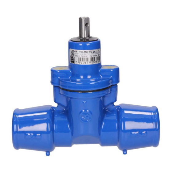
The gate valve can be controlled with:
a handwheel sized according to the Product Specification Sheet and mounted on the gate valve spindle or a
pedestal;
a T-socket wrench, if the spindle neck is in a housing;
an electric or pneumatic drive unit;
other driving gear, e.g. a handwheel with a chain.
Valve control requires a specific driving torque (see table in Section 2) and a specific number of spindle turns. Do
not exceed the maximum driving torque.
To ensure full operational efficiency, carry out a technical inspection and maintenance at least once a year as
follows:
Operate the gate valve from the fully open position to the fully closed position, or vice versa, as the case may
be.
Follow the driving torque limits specified in the table in Section 2.
If the valve operation is difficult, i.e. the valve reaches the maximum driving torque before either of its limit
positions (e.g. due to scale on the spindle threads), repeat the full operation three times.
Check the tightness of all connections and seals with the gate valve closed.
If all the actions above have been completed with a good result, visually inspect the corrosion protection. If
the paint coat is damaged, rebuild it with the paint kits available from JAFAR.
OPERATING MANUAL
DN
3500
3510
L
25
75
95
32
80
100
40
80
105
50
90
110
Tab.1. INSERTION DEPTH
10-2022
7/9