Jafar 4493SA Руководство по эксплуатации - Страница 11
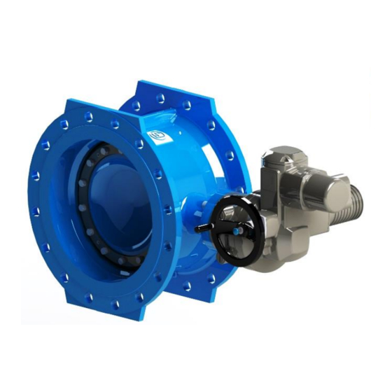
Просмотреть онлайн или скачать pdf Руководство по эксплуатации для Блок управления Jafar 4493SA. Jafar 4493SA 14 страниц. Double eccentric flanged butterfly valve
5.2.
INSTALLATION INSTRUCTIONS
Before installation, the condition of the internal surfaces of the butterfly valve and the surfaces to which the seals
working with the pipeline will be fitted should be checked and, if necessary, thoroughly washed with water. When
mounting butterfly valves between pipeline flanges, first remove any preservatives which may have been used to
protect the surfaces during transport, clean thoroughly the side surfaces of the butterfly valve to which the seal is
to be mounted, install previously prepared seals and fasten the whole assembly with appropriately long bolts or
pins connecting two adjacent flanges. For proper installation, the flange thickness for the selected DN of the
pipeline must be taken into account. When opening the butterfly valve flap it extends beyond the installation
length, therefore it is necessary to remember about free space in the pipeline for proper operation of the flap by
using the appropriate fittings e.g. cast iron stub pipe, assembly insert. The minimum distance from the valve flange
to the end of the gasket dimension is given in the following Table 4 and Fig. 12:
DN
DN200 DN250 DN300
x [mm]
0
DN
DN800 DN900 DN1000 DN1100 DN1200 DN1400 DN1600 DN1800 DN2000
x [mm]
154
Table 4. Dimension "x"
Fig. 12. Preview drawing of a fully open valve 4493 DN1200 PN10
Tighten the connection flange bolts crosswise to ensure a proper seal pressure. Start from the bolt holes near the
valve pivot shaft. The tightening torque of the bolt nuts is specified in the standard PN-63/M-82056. During
mounting, it is necessary to consider making bases or supports for butterfly valves, which must be adapted to the
size and weight of the valve in order to avoid transferring the load into the pipeline. Installed fittings are an integral
part of the pipeline.
OPERATING MANUAL
DN350
0
8
24
184
214
199
DN400
DN450
33
48
274
334
07-2022
DN500
DN600
DN700
63
93
124
394
454
514
11/14