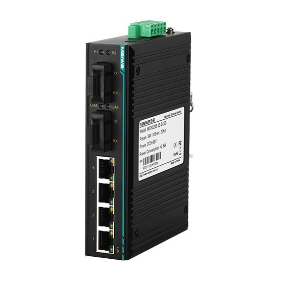
Maiwe MIEN2206 Руководство пользователя - Страница 11
Просмотреть онлайн или скачать pdf Руководство пользователя для Переключатель Maiwe MIEN2206. Maiwe MIEN2206 14 страниц. Unmanaged industrial ethernet switch

MIEN2206 Unmanaged Industrial Ethernet Switch
3.2.2. Cable Connection
After the MIEN2206 series switches are correctly installed, the cables can
be installed and connected, mainly including the cable connections of the
following interfaces.
RJ45 interface
The terminal equipment interface provided by MIEN2206 series switches
is a 10Base-T / 100Base-TX Ethernet RJ45 interface, which uses a DC
network cable to connect to the terminal equipment and a crossover network
cable to connect to the network equipment.
Connecting Power
MIEN2206 series switches use power according to the instructions on the
product label. When all other cables are connected, the power can be
connected
3.2.3. Fiber Connecting
MIEN2206 series switches provide 100Base-FX full-duplex single-mode or
multi-mode fiber interfaces. The type of optical fiber interface can choose SC /
ST / FC according to demand.
Attention
This switch uses a laser to transmit signals on fiber optic cables. The
laser meets the requirements of Class 1 laser products, and normal
operation is not harmful to the eyes. However, when the device is powered
on, do not look directly at the optical transmission port and the end face of
the fiber terminator.
The steps to connect pluggable fiber optic modules are as follows:
Remove and keep the rubber sleeve of the SC / ST / FC port. When not
in use, put on a rubber sleeve to protect the fiber optic terminator
Check whether the fiber terminator is clean. Lightly moisten a clean
paper towel or cotton ball and gently wipe the cable plug. A dirty fiber
terminator will reduce the quality of the optical transmission and affect the port
performance
Connect one end of the optical cable to the optical fiber interface and the
other end to the optical fiber interface of another device
After the connection is completed, please check the LINK / ACT indicator
of the corresponding optical port on the front panel.
Simple test
3.2.4. System Self-check
When the device is powered on, all service port indicators on the front
- 7 -
