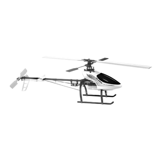
Century Helicopter Products Hummingbird Elite 3D Pro Руководство по эксплуатации - Страница 6
Просмотреть онлайн или скачать pdf Руководство по эксплуатации для Игрушка Century Helicopter Products Hummingbird Elite 3D Pro. Century Helicopter Products Hummingbird Elite 3D Pro 10 страниц.
Также для Century Helicopter Products Hummingbird Elite 3D Pro: Руководство по сборке и эксплуатации (12 страниц)

Section 6
Expert Tips:
To make the setup go easier on transmitters with 5 or more programmable points on
the pitch curve, assuming that the 5 points correspond to low stick, point 1, point 2,
point 3 and high stick. Set points 1,2,3 to 50% which will create a flat pitch curve in
the center that will allow you to consistently find 50% pitch near mid stick. After servo
direction and centering is completed, return points 1 & 3 back to their default values.
For highly aerobatic flying, when the rotor head speed is at 1500rpm or above, bond
the flybar paddles in place using cyanoacrylate glue to the flybar.
Radio Setup Procedure
1. It is best to choose a new model memory (if available) and use the Reset feature
to remove any previous settings or mixes. Remember this usually also returns the
radio configuration to single servo.
2. Locate and activate the swashplate mixing for 120
single servo on channel 6 by default).
3. Return both the aileron and elevator trims and subtrims to center along with any
hover pitch knobs.
Collective Pitch Setup:
4. Power on the transmitter and the helicopter without the motor connected. Power on the model. Center throttle/collective stick to 50%
and find the correct servo arm that is closest to 90
5. Watch as the collective stick is moved that all three servo arms move in the same direction. Any servo that is moving in the wrong
direction should be corrected using the servo reverse function for that channel. Continue until all three servos work together to move
the swashplate in the same direction.
6. Watch as the collective stick is raised that the swashplate moves upwards. If it moves downwards, go to the ccpm swashplate menu
and change the default setting to be opposite, for example, if Pitch is set to +60 then change to -60 and retest.
7. While looking from the back of the helicopter, check that when the elevator stick is moved forward that the swashplate tips forward and
when the aileron stick is moved left the swashplate tips left. If the swashplate moves in the wrong direction, change the direction from
the same ccpm swashplate menu. Change from the default value of +60 to -60 and retest.
8. Now that the servos are moving in the correct directions, the servo horn center position must be trimmed using the internal subtrim
feature to position the arm be about 90 degrees to its pushrod (and to the length of the servo), use the subtrim (or centering feature)
to achieve this angle, be as precise as possible.
9. Carefully remove the three pushrods from the swashplate and verify the length is 25mm from the "z" bend to the center of the ball link.
Remove each servo horn one at a time and drill the last hole (photo) using a #55 drill bit [1.34mm or 0.052"] that locates the pushrod
at 11-12mm from the center of the servo arm pivot point.
10. Now that the basic radio setup procedure is completed, return to your pitch curve function and restore points 1 & 3 to their default
values, usually 25% and 75%. Move the collective stick from low to high and watch the swashplate, if the swashplate bends at the low
or high position, reduce the pitch value in the ccpm menu, for example if the value is -60 try -55 and repeat the test. Continue until the
swashplate moves to the limits.
11. Move the cyclic (aileron and elevator) sticks to the full horizontal and diagonal positions and see if the swashplate is binding against
the main shaft. If it does, return to the ccpm menu and reduce the value for the servo that is binding. While holding the cyclic stick in
the corner, slowly rotate the rotor head and again watch the swashplate for binding.
Section 7
When the main shaft turns clockwise the tail rotor should also turn. If the tail does not turn or if it seems to skip, check the gears
inside the tail boom and gearbox. Right rudder input should turn the nose to the right. Left rudder input should turn the nose to the
left. The servo controlling the rudder is mounted on the tail boom just aft of the main mechanics. The Rudder servo mount clamps to
the tail boom and holds the servo in place with two screws. Make sure the grip of the clamp is secure so the mount cannot shift in any
direction.
Rudder servo mount
with rudder servo
installed.
The servo arm should be positioned for
maximum travel range. setting the servo arm
at a 90 degree angle to the tail boom will give
equal (maximum total) travel distance on both
ends of the servo travel range.
6
eCCPM Radio Setup
ccpm (most manufacturers set
0
degrees (slightly up or down is ok).
0
Tail Setup: Tail Pushrod, Servo And
Blade Grips
Tail blade
grips
The only way to get perfect tail control
is to test your settings and adjust until
the helicopter responds equally for both
directions of rudder control. Keep in mind
that the tail is compensating for main rotor
torque. Note: main rotor torque turns the
helicopter counter-clockwise.
Heli Front/Nose
Pitch
Heli Rear/Tail
The Pushrod for tail
changes tail blade pitch
and should be adjusted for
roughly equal pitch in both
directions as a starting
point.
Tail pushrod
*see page
5, step 8
Aileron
Elevator
Oil Here
Place a tiny bit of oil (any good
lubricant for metal on metal) on
the tail output shaft. This will
keep the tail pitch slider sliding
smoothly on the output shaft.
