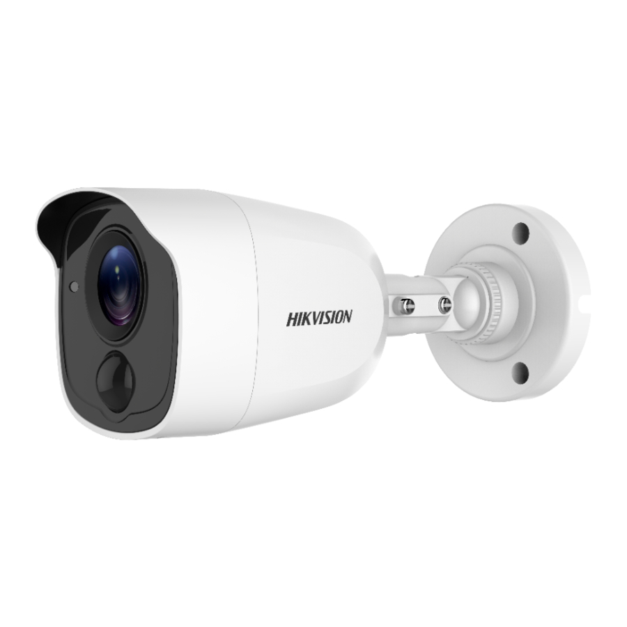
HIKVISION TURBO HD D0T PIR Series Руководство пользователя - Страница 9
Просмотреть онлайн или скачать pdf Руководство пользователя для Камера безопасности HIKVISION TURBO HD D0T PIR Series. HIKVISION TURBO HD D0T PIR Series 16 страниц.

Note:
Drill the cable hole in the center of the drill template,
when adopting ceiling outlet to route the cable;
3. Route the cables through the cable hole (optional)
or the side opening;
4. Fix the camera to the ceiling with supplied screws;
Figure 2-9 Fix the amera to the eiling
Note:
The supplied screw package contains self-tapping
screws, and expansion bolts.
For cement wall/ceiling, expansion bolts are
required to fix the camera. For wooden
wall/ceiling, self-tapping screws are required.
5. onnect the corresponding power cord, and video
cable;
6. Power on the camera to check whether the image
on the monitor is gotten from the optimum angle; If
not, adjust the surveillance angle;
Rotation Position
[0° to 360°]
1)
Loosen the No;1 adjusting screw to adjust the pan
position [0° to 360°\; Tighten the No;1 adjusting
screw;
2)
Loosen the No;2 adjusting screw to adjust the
tilting position [0° to 180°\; Tighten the No; 2
adjusting screw;
3)
Loosen the No;3 adjusting screw to adjust the
rotation position [0° to 360°\; Tighten the No;3
adjusting screw;
Ceiling/Wall Mounting with Junction Box
2.2.2
Before you start:
You need to purchase a junction box separately;
Steps:
1. Paste the drill template on the ceiling/wall;
Available from A1 Security Cameras
w.a1securitycameras.com email: sales@a1securitycamera
Screw Hole
Screw Hole
Template
Side Opening
Figure 2-8 Drill Template
Figure 2-10 3-!xis !djustment
Ø 55 mm
Screw Hole
Pan Position
[0° to 360°]
1
Tilt Position [0° to 180°]
2
3
( 2.17" )
Ø 68 mm
( 2.68" )
Ø 18 mm
( 2.68" )
