CORNING EDGE8 MTP Установка и тестирование - Страница 3
Просмотреть онлайн или скачать pdf Установка и тестирование для Блок управления CORNING EDGE8 MTP. CORNING EDGE8 MTP 13 страниц. Tap module
4.
Connector and Adapter Cleaning
4.1
Cleaning the LC adapters with an LC port cleaner
before each mating is recommended (Figure 2).
4.2
The use of an MTP Connector and Port
Cleaning Tool to clean MTP connectors and ports
before each mating is recommended (Figure 3).
5.
The Functionality of the Tap Module Splitters
Directionality
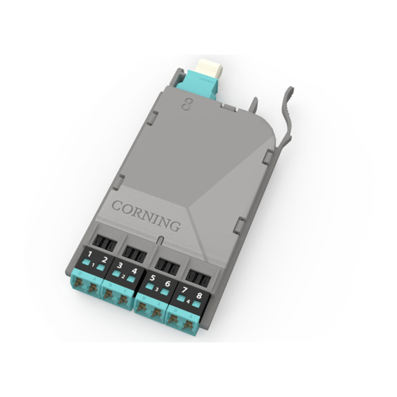
5.1
In simplest terms, the splitters inside an MTP Tap module act like a divider of a one-way traffic
flow – in this case, light.
The module has two Live ports which interface with the network. Each of these ports have eight fibers,
of which four are TX and four are RX ports. In the case of TX fibers, these are the input to the splitters
with the two outputs of the splitters going to the other Live port and Tap port as shown in Figure 4.
Live Output (RX)
on four of eight bers
Tap Output (RX)
on four of eight bers
HPA-0995-EDGE8
In the same fashion, the Live port on the front of the modules serves as an input for the six additional
splitters. The output of those splitters route to the Live port in the rear of the module and the Tap port,
as shown in Figure 5).
Live Source (TX)
on four of eight bers
Tap Output (RX)
on four of eight bers
HPA-0996-EDGE8
Tables 2 through 5 in Sections 8 and 9 provide a full representation of the source and output positions.
STANDARD RECOMMENDED PROCEDURE 003-139-AEN | ISSUE 1 | JANUARy 2017 | PAGE 3 OF 13
HPA-0738
HPA-0754
Figure 2
Figure 3
Live Source (TX)
on four of eight bers
Figure 4
Live Output (RX)
on four of eight bers
Figure 5