E-T-A ControlPlex CPC12EC Руководство по установке - Страница 3
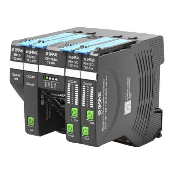
Просмотреть онлайн или скачать pdf Руководство по установке для Контроллер E-T-A ControlPlex CPC12EC. E-T-A ControlPlex CPC12EC 4 страницы. Bus controller

XF1/XF2 EtherCAT-Schnittstelle
Typ:
Bei der Verdrahtung und dem Anschluss an das Bussystem
EtherCAT
ist die Installationsrichtlinie (ETG.1600) der EtherCAT
®
Technology Group zu beachten.
X1 Ethernet-Schnittstelle
Typ:
Kommunikationsschnittstelle zum Web-Server
Betriebsart
Signalisierung der Betriebsart
LED US1
EtherCAT
----
Init-State
EtherCAT Pre-
----
Operational-
State
EtherCAT Safe-
----
Operational-
State
EtherCAT
----
Operational-
State
EtherCAT
----
Fehler
Kein EtherCAT
----
Fehler
Spannungs-
grün
versorgung OK
Firmware
aus
Update
Keine
----
Aktorspannung
Kein ange-
----
schlossenes
Gerät oder
Bus-Fehler
LED US1: Bei angelegter Versorgungsspannung an XD1
leuchtet die LED US1 grün.
LED US2: Bei angelegter Versorgungsspannung an das
EM12 leuchtet die LED US2 grün, ohne Spannung rot. An-
zeigemöglichkeit: Rot, Grün, Orange
LED ERR: Die LED ERR zeigt Fehler bei der EtherCAT-Kom-
munikation an, LED Anzeigemöglichkeit: Rot
LED RUN: Die LED RUN zeigt den aktuellen EtherCAT-Zu-
stand an, LED Anzeigemöglichkeit: Grün
Hinweis:
Ausführliche
ter, Softwaretools sowie gerätespezifische Gerätedateien
(ESI-Dateien ) sind auf der E-T-A Homepage zum Download
bereitgestellt. Stellen Sie sicher, dass Sie immer mit den ak-
tuellen Dokumenten arbeiten.
EtherCAT
ist eine eingetragene Marke und patentierte Tech-
®
nologie lizenziert durch die BeckhoffAutomation GmbH,
Deutschland.
RJ45-Buchse
RJ45-Buchse
LED US2
LED ERR
LED RUN
----
----
aus
----
----
grün
Blinkend
0,2 s An/
0,2 s Aus
----
----
grün
Blinkend
0,2 s an/
1 s aus
----
----
grün
----
rot
----
----
aus
----
----
----
----
aus
aus
aus
rot
----
----
orange
----
----
blinkend
0,5 s an/
0,5 s
aus
Handbücher,
Produktdatenblät-
XF1/XF2 EtherCAT Interface
Type:
When wiring and connecting to the bus system EtherCAT® the instal-
lation and wiring regulations (ETG.1600) of the EtherCAT Technology
Group have to be observed.
X1 Ethernet Interface
Type:
communication interface to web server
Operating
Indication of operating mode
mode
LED US1
EtherCAT
----
Init-State
EtherCAT Pre-
----
Operational-
State
EtherCAT Safe-
----
Operational-
State
EtherCAT
----
Operational-
State
EtherCAT Error
----
No EtherCAT
----
Error
Operating
green
Voltage OK
Firmware
off
Update
No Actuator
----
Voltage
No Device
----
Connected Or
Bus Error
LED US1: The LED US1 lights up green if supply voltage is
applied to XD1.
LED US2: The LED US2 lights up green if supply voltage is
applied to EM12, otherwise red. LED colour options: red,
green, orange
LED ERR: The LED ERR indicates EtherCAT-communication
errors, LED colour options: red
LED RUN: The LED RUN indicates current EtherCAT-state,
LED colour options: green
Note: Detailed user manuals, data sheets, software tools and
product-specific device files (ESI files) are available on the
E-T-A homepage for download. Please make sure to always
use the most recent documents.
EtherCAT
is a registered trademark and patented technology,
®
licensed by Beckhoff Automation GmbH, Germany.
RJ45 female connector
RJ45 female connector
LED US2
LED ERR
LED RUN
----
----
off
----
----
green
Flashing
0.2 s on/
0.2 s off
----
----
green
Flashing
0.2 s on/
1 s off
----
----
green
----
red
----
----
off
----
----
----
----
off
off
off
red
----
----
orange
----
----
flashing
0.5 s on/
0.5 s off
