Fronius 63A-1 Краткое руководство - Страница 4
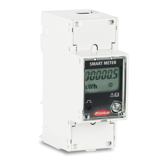
Просмотреть онлайн или скачать pdf Краткое руководство для Сварочная система Fronius 63A-1. Fronius 63A-1 20 страниц. Smart meter
Также для Fronius 63A-1: Краткое руководство (17 страниц), Краткое руководство по эксплуатации (2 страниц), Краткое руководство по эксплуатации (2 страниц), Краткое руководство по эксплуатации (8 страниц), Краткое руководство по эксплуатации (10 страниц)
2. INSTALLING AND ACTIVATING A FRONIUS SMART METER
2.1 Schematics and Wiring Requirements
/ Wiring between Fronius Smart meter and inverter should use a CAT5 or CAT6 cable.
Important:
To be compliant with the AS3000 standards, it is recommended to have the CAT5/CAT6 cable
in a heat shrink tubing (probably 10mm) when it enters the switchboard part or alternatively use a 240V
rated CAT5/CAT6 cable (e.g. Clipsal CBUS cable).
/ Connection is a data line for Modbus RTU / RS485 using screw terminals on the meter
/ Maximum distance: 300 m (980 feet)
/ Use a single core per terminal connection between Fronius Smart Meter and the inverter. For D+ and D- use
the single cores from the same colour (e.g. D+ is orange/white, D- is orange)
Meter connection on the Datamanager 2.0
The meter needs to be connected to the Datamanager's terminal block using terminals D+, D- and -.
4/19
(c) Fronius International GmbH, 2020