Garmin GMA 340 Руководство по установке - Страница 24
Просмотреть онлайн или скачать pdf Руководство по установке для Дисплей авионики Garmin GMA 340. Garmin GMA 340 43 страницы. Audio panel
Также для Garmin GMA 340: Руководство пилота (12 страниц), Дополнительное руководство по эксплуатации (10 страниц), Руководство пилота (4 страниц), Руководство пилота (8 страниц), Руководство пилота (8 страниц), Руководство пилота (12 страниц)

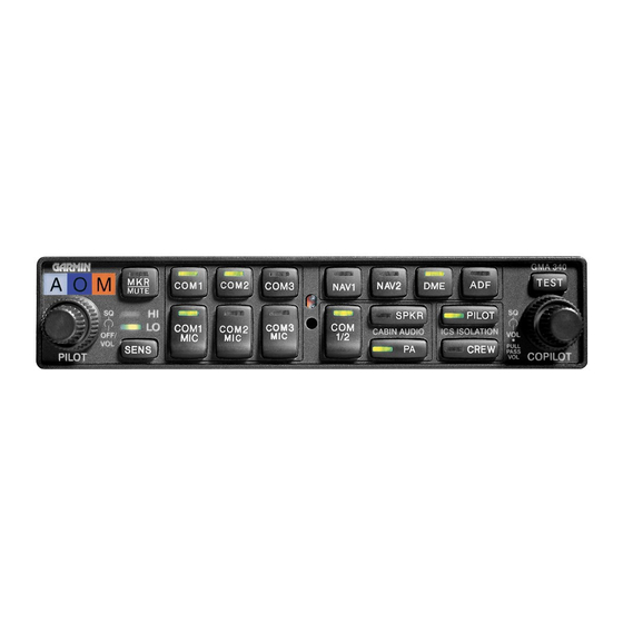
13. Transceiver Audio Selector Buttons (COM 1, COM 2, COM 3)
14. Transmitter (Audio/Mic) Selection Buttons
15. Split COM Button (SPKR in Dual ADF)
16. Aircraft Radio Audio Selection Buttons (NAV1, NAV2, DME, ADF)
17. Annunciator Test Button
18. Locking Screw Access
19. Photocell – Automatic Annunciator Dimming
3.1.2
On, Off, and Failsafe Operation
The GMA 340 is powered off when the left small knob (figure 3-1, item 5) is rotated fully CCW into the detent.
To turn the unit on rotate the knob clockwise past the click. The knob then functions as the pilot's ICS volume
control. A failsafe circuit connects the pilot's headset and microphone directly to COM 1 in case the power is
interrupted or the unit is turned off. Refer to the note in paragraph 2.6.2.
3.1.3
Lighting
The intensity of the button annunciators and marker beacon LEDs are controlled automatically by a built-in
photocell (19) on the front panel. Nomenclature backlighting is controlled by the aircraft dimmer bus. See
installation wiring diagrams in Appendix B for guidance on connecting the dimmer bus to the GMA 340.
3.1.4
Transceivers
Audio level is controlled by the selected com radio volume control.
Selection of either COM 1, COM 2, or COM 3 (13) for both MIC and audio source is accomplished by pressing
either COM 1 MIC, COM 2 MIC, or COM 3 MIC (14). The active com audio is always heard on the headphones.
Each audio source can be selected independently by pressing COM 1, COM 2, or COM 3 (13). When selected in
this way, they remain active as audio sources independently of which transceiver has been selected as the active
microphone source.
When a microphone is keyed, the active transceiver's MIC button LED blinks approximately once per second to
indicate the transmitter is active.
When no aircraft radio activity is detected by the GMA 340, the amount of ambient background noise from the
radios is further reduced by the MASQ
3.1.7). If this feature is not desired, then J1 pin 16 (MASQ INH*) should be tied to ground.
Page 3-2
Rev. L
NOTE
TM
circuit. This processing is also applied to the Nav radios (described in
GMA 340 Installation Manual
190-00149-01
