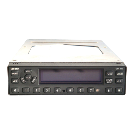
Garmin GTX GTX 330D Руководство по установке - Страница 15
Просмотреть онлайн или скачать pdf Руководство по установке для Дисплей авионики Garmin GTX GTX 330D. Garmin GTX GTX 330D 49 страниц. Mode s transponder
Также для Garmin GTX GTX 330D: Дополнение к руководству пилота (50 страниц), Дополнение к руководству пилота (50 страниц), Руководство пилота (13 страниц), Руководство пилота (13 страниц)

3.
INSTALLATION PROCEDURE
3.1
ANTENNA INSTALLATION
3.1.1 Antenna Installation
Install the antenna according to the antenna manufacturer's instructions and FAA AC 43.13-2A.
3.1.2 Antenna Cable Connectors
The antenna cable requires a BNC connector at the antenna and a male BNC "Blindmate" connector
(P/N 330-00053-01, supplied with GTX 330 backplate assembly, 011-00582-00/01 at the transponder. Follow BNC
connector manufacturer instructions for assembly of the BNC connector.
3.2
ELECTRICAL CONNECTIONS
All electrical connections, except for the antenna, are made through a single, 62 pin D-subminiature connector.
Figure 2-1 defines the electrical characteristics of all input and output signals and identifies the cable requirements
for each signal. Required connector and associated hardware are supplied in the connector kit (P/N 011-00583-00).
See figures 4-1 and 4-2 for interconnect wiring diagrams.
Check wiring connections for errors before inserting the GTX 330 into the rack.
Incorrect wiring could cause internal component damage.
1. Insertion/extraction tools from ITT Cannon are all plastic; others are plastic with metal tip.
Non-GARMIN part numbers shown are not maintained by GARMIN and consequently are subject to
2.
change without notice.
3. All wires must be passed through the backshell before being assembled to connector.
GTX 330 Installation Manual
190-00207-02
CAUTION
Pin Contact Part Numbers
Wire Gauge
GARMIN P/N
Military P/N
Recommended Crimp Tools
Wire Gauge
Hand Crimping
Tool
Military P/N
M22520/2-01
Positronic
9507
ITT Cannon
995-0001-584
AMP
601966-1
Daniels
AFM8
Astro
615717
62 pin connector (P3301)
22-28 AWG
336-00021-00
M39029/58-360
20-24 AWG
Positioner
Insertion/
Extraction Tool
M22520/2-08
M81969/1-02
9502-5
M81969/1-02
995-0001-604
980-2000-426
601966-5
91067-2
K13-1
M24308/1-02
615724
M81969/1-02
NOTES
Page 3-1
Rev. 1
