Garmin GPSMAP 17 Руководство по установке - Страница 7

Просмотреть онлайн или скачать pdf Руководство по установке для Морская система GPS Garmin GPSMAP 17. Garmin GPSMAP 17 16 страниц. Gps receiver/antenna
Также для Garmin GPSMAP 17: Руководство по установке (16 страниц), Руководство по установке (12 страниц), Справочное руководство (1 страниц), Технический справочник (30 страниц), Руководство по установке (17 страниц), Руководство по установке (19 страниц), Декларация о соответствии (1 страниц), Технические характеристики (40 страниц), Краткое руководство по эксплуатации (16 страниц)
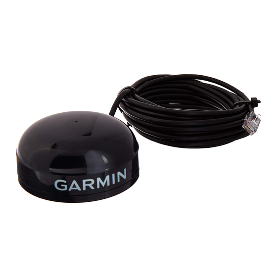
Garmin GPSMAP 17 Руководство по установке

Mounting Location Tips

• Position the receiver so that it has the clearest
possible view of the sky and horizon in all directions.
• Avoid mounting the antenna next to large areas of
conductive material (metal, aluminum, etc.) as this
may cause poor signal reception.
• Do not mount the GPS 17 high on a mast, as the top
of the mast travels more than the boat. The unit will
provide more stable readings if it is located near the
water level.
• When routing the wiring to the GPS 17, avoid routing
the cable near the vessel's alternator or ignition
system components or parallel to other power lines.
• As a general rule, mount the receiver at least three
feet from all other antennas and the vessel's electrical
system components (alternator/ignition system).
• The GPS 17 is supplied with a 30-foot power/data
cable. Be sure that the cable can be routed to the
necessary devices.
GPS 17 Installation Guide
To flush mount the GPS 17:
1. Turn the GPS 17 upside down. To create a template,
punch a hole in the three mounting screw holes.
2. Use the template to mark the hole locations on the
mounting surface. The centers of the holes are 2.44"
(62 mm) apart. Use an 11/64" drill bit to drill a hole at
each marked location.
3. Align the GPS 17 over the three holes and fasten the
M4 screws. The threads are 8.10 mm deep: do not
use screws that will thread into the base any deeper,
as this may damage the GPS 17.
Mounting
hole
Mounting hole
Figure 1: Bottom of GPS 17 Base
M
GPS 17
OUNTING THE
Mounting hole
3