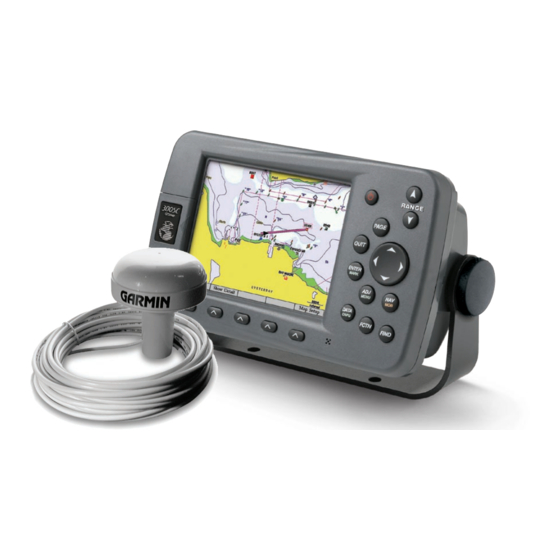
Garmin GPSMAP 3005C Руководство по установке - Страница 7
Просмотреть онлайн или скачать pdf Руководство по установке для Морская система GPS Garmin GPSMAP 3005C. Garmin GPSMAP 3005C 10 страниц. Declaration of conformity
Также для Garmin GPSMAP 3005C: Краткое справочное руководство (2 страниц), Руководство по шаблонам (1 страниц), Краткая справка (2 страниц), Руководство по установке (17 страниц), Декларация о соответствии (1 страниц)

Garmin
GPSMAP 3000 Series
Chartplotter
Garmin
GPSMAP 3000 Series
Chartplotter
GPSMAP 3000 Series Chartplotter Wired to a NMEA Device With Two-way Communication
Garmin
GPSMAP 3000 Series
Chartplotter
GPSMAP 3000 Series Chartplotter Wired to a NMEA Device With One-way Communication
Garmin
GPSMAP 3000 Series
Chartplotter
GPSMAP 3000 Series Installation Instructions
Fuse
GPSMAP 3000 Series Chartplotter Wired to a GPS 17x
Fuse
3A
>
>
>
>
Fuse
3A
>
Fuse
*DB-9 serial PC connectors typically have pin numbers printed next to each pin.
GPSMAP 3000 Series Chartplotter Wired to a DB-9 Serial PC Connector
+
Battery
Wire
10-33 Vdc
Color
3A
Red
Black
Unconnected
Orange
Green
>
White
>
�
�
Battery
Wire
10-33 Vdc
Color
Red
Black
Blue (port 1)
Brown (port 1)
OR
Gray (port 2)
Violet (port 2)
�
�
Battery
10-33 Vdc
Wire
Color
Red
Black
Blue (port 1)
OR
Gray (port 2)
�
Battery
10-33 Vdc
Wire
Color
3A
Red
Black
Brown (port 1)
>
Blue (port 1)
>
-
Wire
Fuse
Color
1A
Red
Black
White/
Orange
White/Red
Purple
Orange
White
>
Gray
>
Wire
Type
Power
Ground
NMEA TX/RX- (B)
NMEA Rx + (A)
>
NMEA Tx + (A)
>
Wire
Type
Power
NMEA RX- (B)
NMEA Rx + (A)
>
�
DB-9 Pin
Numbers
Pin 5: Ground (SG)
Pin 3: Transmit (TxD)
Pin 2: Recieve (RxD)
GPS 17x
NMEA Device with
Sonar Output/VHF
Radio with DSC
NMEA Device/
Autopilot (Input Only)
DB-9 Serial
PC Connector*
6
2
7
3
�
4
9
5
End view
7
