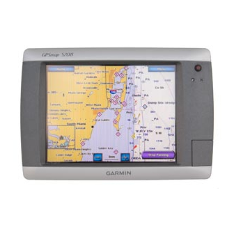
6. Place the chartplotter in the hole, and make sure that the mounting holes on the chartplotter line up with the pilot holes on the flush-mount
template after cutting, sanding, and filing the hole. If they do not, mark the locations where the pilot holes need to be.
7. Using the center punch, indent the center of each of the mounting-hole locations.
8. Using the
3
/
inch drill bit, drill the mounting holes.
8
NOTE:
If you are mounting the chartplotter in fiberglass, it is recommended to use a countersink bit to drill a clearance-counterbore through only the top
gel-coat layer. This will help to avoid any cracking in the gel-coat layer when the screws are tightened.
9. Install the rubber gasket on the back of the chartplotter. The top and bottom sections will line up with the holes. The side sections will line up
with the notches in the case for the sun cover.
NOTE:
To prevent corrosion of the metal contacts, cover unused connectors
10. P lace the chartplotter into the cutout.
11. S ecurely tighten the included mounting screws through the chartplotter into the pilot holes.
NOTE:
Stainless-steel screws may bind when screwed into fiberglass and overtightened. Garmin recommends applying an anti-galling, stainless anti-
seize lubricant to the screw before using.
12. R eplace the mounting covers by snapping them into place.
Be sure to follow the correct mounting directions and the correct wiring directions for the antenna included with your chartplotter.
You can surface mount the antenna, attach it to a standard marine pole mount, or install the antenna under fiberglass.
Mounting Location Considerations
To ensure the best reception, keep these considerations in mind while selecting a mounting location.
• Mount the antenna in a location that has a clear, unobstructed view of the sky in all directions.
• Mount the antenna where it is not covered by the superstructure of the boat, a radar device, or
a mast
.
➊
• Higher mounting locations provide better reception.
• Do not install the antenna near sources of electromagnetic interference (EMI)
motor or other large marine electronics.
• Install the antenna at least 3 ft. (1 m) away from the path of a radar beam or VHF radio
antenna
.
➌
• It is best to install the antenna above the path of the radar beam
• It is acceptable to install the antenna under the path of the radar beam
• Install the antenna at least 2 in. (5 cm) from a magnetic compass to avoid interfering with the
compass.
Verifying a Mounting Location
1. Select a mounting location.
2. Temporarily secure the antenna in the selected location.
3. Test the antenna for correct operation on the chartplotter.
4. If you experience interference with other electronics, try a different location.
5. Repeat steps 3 and 4 until you find a mounting location where the antenna operates correctly.
After you verify correct operation at the mounting location, permanently mount the antenna.
GPSMAP 4000/5000 Series Installation Instructions
Mounting the GPS 17x Antenna
notice
➍
(page
20) with the attached weather caps.
, such as the
➋
.
.
➎
➊
➋
➍
➌
➎
5

