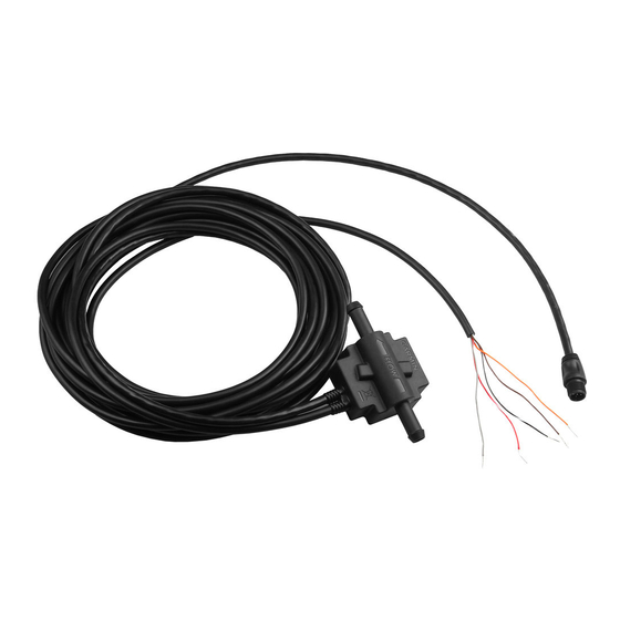
Step 3: Connecting the GFS 10 to the Power Source and the Fuel Gauge
The GFS 10 must be connected to the power source of the boat. The GFS 10 can be optionally connected to the fuel gauge on your boat to
read fuel-level data. The bare-wire cable contains the power and ground wires, as well as the wires you connect to your fuel gauge. Follow the
wiring diagram to complete the connections.
Fuel gauge connection optional
IMPORTANT:
•
If you use a fuse block on your boat, cut the fuse holder from the power wire. Use a .25 A fuse in the fuse block.
•
Install the fuse holder as close to the battery as possible. If an extended run of wire is needed, add 24 AWG wire between the fuse
holder and the GFS 10, not between the fuse holder and the battery.
•
DO NOT install the fuse holder near the gas tank.
•
If you do not connect the GFS 10 to a fuel gauge or level-sensor on a fuel tank, connect the brown wire to ground.
Notes:
•
Consult the Owner's Manual provided by your boat manufacturer to determine the ground, ignition, and level-sensor connections on
your fuel gauge. Often, the ignition connector is labeled "I" or "+", and the level-sensor connector is labeled "S."
•
If you do not have a fuel gauge, but you do have a fuel tank with a level sensor, you can connect the brown wire to the "+" terminal
of the level sensor at the tank. DO NOT install the fuse holder near the tank—extend the brown wire to the tank with 24 AWG wire.
Complete this connection before completing any other wiring connections to reduce the risk of a spark near the fuel tank.
•
If you are using NMEA 2000, be sure to leave the orange wire unconnected.
Multiple GFS 10 Devices
If your boat has more than one engine or fuel tank, you will need multiple GFS 10 devices. Each GFS 10 can function as one flow sensor and
one level sensor. You need one GFS 10 flow sensor for each engine, and one GFS 10 level sensor for each fuel gauge or fuel tank with a level
sensor. Depending on your boat, you may use only the flow-sensing capabilities of additional GFS 10 devices.
Flow Sensing
Multiple engines
Multiple fuel tanks for one engine
Level Sensing Multiple tanks with one fuel gauge and a manual switch
Multiple fuel tanks with multiple gauges
Multiple fuel tanks with no fuel gauge
GFS 10 Installation Instructions
-
12 Vdc
Battery
Ground
Ignition
Fuel Tank
Level Sensor
Unconnected
(when using NMEA 000)
To NMEA 000 Network
+
or CANet Bus
Wire
Color
Fuse
Red/White
.25 A
Black/White
Grey
Brown
Orange
One GFS 10 per engine–up to four engines
One GFS 10 per engine–install after the tank switch
One GFS 10 wired to the fuel gauge
One GFS 10 per tank–wired to each gauge–up to two tanks
One GFS 10 per tank–wired to the level sensor (if available)–up to two tanks
I
I
nstallatIon
nstructIons

