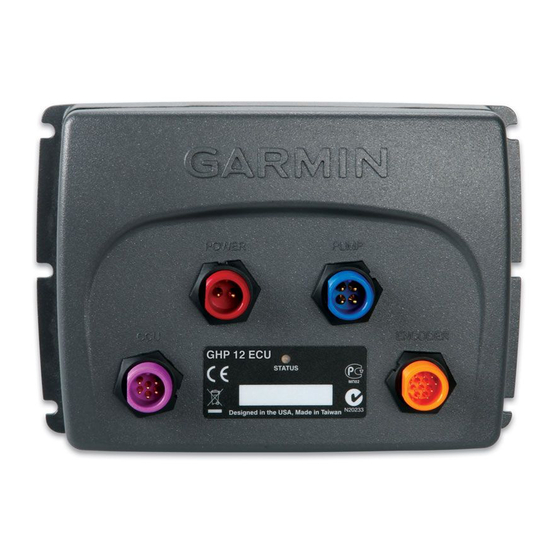
Garmin GHP 12 Руководство по установке - Страница 13
Просмотреть онлайн или скачать pdf Руководство по установке для Морское оборудование Garmin GHP 12. Garmin GHP 12 32 страницы. Drive unit and rudder feedback unit wiring reference
Также для Garmin GHP 12: Справочное руководство (2 страниц)

Connecting the CCu to an Existing nMEa 2000 network
1. Determine where to connect the CCU ➊ to your existing NMEA
2000 backbone ➋.
2. Disconnect one side of a NMEA 2000 T-connector from the
network.
3. If necessary, to extend the NMEA 2000 network backbone, connect
a NMEA 2000 backbone extension cable (not included) to the side
of the disconnected T-connector.
4. Add the included T-connector ➌ for the CCU to the NMEA
2000 backbone by connecting it to the side of the disconnected
T-connector or backbone extension cable.
5. Route the included drop cable ➍ to the bottom of the T-connector
added in step 4, and connect it to the T-connector.
If the included drop cable is not long enough, you can use a drop
cable up to 20 ft. (6 m) long (not included).
6. Connect the drop cable to the to the CCU.
GHP 12 Installation Instructions
➊
➍
➌
➋
Building a Basic nMEa 2000 network for the GHC 10 and
the CCu
You must connect the included NMEA 2000 power cable to the boat
ignition switch, or through another in-line switch. The GHC 10 will
drain your battery if the NMEA 2000 power cable is connected to the
battery directly.
1. Connect the three T-connectors ➊ together by their sides.
➍
-
+
➌
➋
➊
➑
2. Connect included NMEA 2000 power cable ➋ to a 12 Vdc power
source ➌ through a switch.
Connect to the ignition switch ➍ of the boat if possible, or through
an in-line switch (not included).
3. Connect the NMEA 2000 power cable to one of the T-connectors.
4. Connect one of the included NMEA 2000 drop cables ➎ to one of
the T-connectors and to the GHC 10 ➏.
5. Connect the other included NMEA 2000 drop cable to the other
T-connector and to the CCU ➐.
6. Connect the male and female terminators ➑ to each end of the
combined T-connectors.
NOTE: The GHC 10 must connect to the CCU with the yellow
CCU signal wire in the GHC 10 data cable. The black wire must
connect to CCU ground
(page
Notice
➏
➎
12).
➐
➑
13
