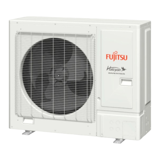
Fujitsu 24LMAS1 Руководство по установке - Страница 6
Просмотреть онлайн или скачать pdf Руководство по установке для Кондиционер Fujitsu 24LMAS1. Fujitsu 24LMAS1 17 страниц. Outdoor unit

3.3. Mounting the unit
• Install 4 anchor bolts at the locations indicated with arrows in the figure.
• To reduce vibration, do not install the unit directly on the ground. Install it on a secure
base (such as concrete blocks).
• The foundation shall support the legs of the unit and have a width of 2 in (50 mm)
or more.
• Depending on the installation conditions, the outdoor unit may spread its vibration
during operation, which may cause noise and vibration. Therefore, attach damping
materials (such as damping pads) to the outdoor unit during installation.
• Install the foundation, making sure that there is enough space for installing the
connection pipes.
• Secure the unit to a solid block using foundation bolts. (Use 4 sets of commercially
available M10 bolts, nuts, and washers.)
• The bolts should protrude 13/16 in (20 mm). (Refer to the figure.)
• If overturning prevention is required, purchase the necessary commercially available
items.
[Unit: in (mm)]
5-13/16
(147)
25-9/16 (650)
1-15/16
AIR
(50)
• Do not install the outdoor unit in two-stage where the drain water could freeze. Oth-
erwise the drainage from the upper unit may form ice and cause a malfunction of the
lower unit.
• When the outdoor temperature is 32 °F (0 °C) or less, do not use the accessory drain
pipe.
If the drain pipe is used, the drain water in the pipe may freeze in extremely cold
climate.
• If the unit is installed in a region that is exposed to
high winds, freezing conditions, freezing rain, snow
fall or heavy snow accumulation, take appropriate
measures to protect it from those elements.
To ensure stable operation, the outdoor unit must
be installed on a raised stand or rack, at or above
the anticipated snow depth for the region.
The installation of snow hoods and drift preven-
2 in
(50 mm)
tion fencing is recommended when blowing and
Base
or more
drifting snow is common to the region.
3.4. Drain installation
• Perform drain work in accordance with this Manual, and ensure that the drain water
is properly drained. If the drain work is not carried out correctly, water may drip down
from the unit, wetting the furniture.
• When the outdoor temperature is 32 °F (0 °C) or less, do not use the accessory drain
pipe. If the drain pipe is used, the drain water in the pipe may freeze in extremely
cold weather.
• If you are installing the drain pipe and drain caps,
please provide a working space under the base of
the outdoor unit.
• As the drain water flows out of the outdoor unit
during heating operation, install the drain pipe and
connect it to a commercial 5/8 in (16 mm) hose.
(Reverse cycle model only)
• When installing the drain pipe, plug all the holes
other than the drain pipe mounting hole in the
bottom of the outdoor unit with putty so there is no
water leakage. (Reverse cycle model only)
En-6
5-5/8
(143)
1-15/16
(50)
Bolt
CAUTION
CAUTION
Drain pipe mounting hole
Base of the outdoor unit
Drain pipe
[Unit: in (mm)]
1-7/8 (49)
3.5. Pipe installation
3.5.1. Opening a knock out hole
• Be careful not to deform or scratch the panel while opening the knock out holes.
• To protect the piping insulation after opening a knock out hole, remove any burrs
from the edge of the hole. It is recommended to apply rust prevention paint to the
edge of the hole.
Nut
Block
• Pipes can be connected from 4 directions, front, lateral side, rear side and bottom.
(Fig. A)
• When connecting at the bottom, remove the service panel and piping cover on the
front of the outdoor unit, and open the knock out hole provided at the bottom corner
of the piping outlet.
• It can be installed as shown on "Fig. B" cutting out the 2 slits as indicated on "Fig. C".
(When cutting slits, use a steel saw.)
Fig. A
Service cover
Front
connection
Fig. B
Slit
Drain cap mounting hole ×3
Drain pipe mounting
hole ×1
AIR
10-1/2
(267)
13-7/8 (352)
26-3/4 (680)
CAUTION
Lateral
Bottom
connection
connection
Fig. C
Slit
Bottom
connection
Rear
connection
