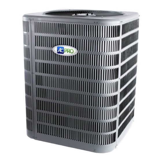
AC Pro 4AC16 Руководство по установке - Страница 3
Просмотреть онлайн или скачать pdf Руководство по установке для Кондиционер AC Pro 4AC16. AC Pro 4AC16 9 страниц.
Также для AC Pro 4AC16: Руководство по установке (9 страниц)

Clearance Requirements
When installing, allow sufficient space for airflow clearance,
wiring, refrigerant piping, and service. For proper airflow,
quiet operation and maximum efficiency. Position so water,
snow, or ice from roof or eaves cannot fall directly on unit.
Figure 1. Clearance Requirements
Do Locate the Unit:
•
With proper clearances on sides and top of unit (a
minimum of 12" on the three sides, service side should
be 24" and 48" on top
•
On solid, level foundation or pad
•
To minimize refrigerant line lengths
Do Not Locate the Unit:
•
On brick, concrete blocks or unstable surfaces
•
Near clothes dryer exhaust vents
•
Near sleeping area or near windows
•
Under eaves where water, snow or ice can fall directly
on the unit
•
With clearance less than 2 ft. from a second uni
•
With clearance less than 4 ft. on top of unit
Indoor Coil Piston Selection
The outdoor section must be matched to a factory approved
indoor section. It is mandatory that the installer ensure that
the correct piston or TXV is installed in the indoor section.
If necessary remove the existing piston and replace it with
the correct piston or TXV. See indoor unit instructions
for details of changing the piston or TXV. Contact your
distributor for accessory piston kits.
The correct piston size is shipped with the outdoor unit,
and also listed in the specification sheet. Do not use the
piston that comes with the indoor unit, unless it matches
the one listed on the outdoor unit.
507043-03
Refrigeration Line Sets
Use only refrigeration grade copper tubes. Split systems
may be installed with up to 50 feet of line set (no more than
20 feet verticle) without special consideration (see long
line set guide lines).
Do not leave the lines open to the atmosphere for any
period of time, moisture, dirt and bugs may contaminate
the lines.
Model
Liquid
Line
18
3/8 or 1/4
24
3/8 or 1/4
30
3/8
36
3/8
41
- -
42
3/8
47
- -
48
3/8
59
- -
60
3/8
* Fittings should be supplied by the installer.
1.
For lines 25 Ft or over, use 3/8"
2.
For lines 25 Ft or over, use 3/4"
3.
For lines 25 Ft or over, use 7/8"
4.
For lines 25 Ft or over, use 1 1/8"
Installation of Line Sets
DO NOT fasten liquid or suction lines in direct contact with
the floor or ceiling joist. Use an insulated or suspension
type of hanger. Keep both lines separate, and always
insulate the suction line. Long liquid line runs (30 feet or
more) in an attic will require insulation. Route refrigeration
line sets to minimize length.
DO NOT let refrigerant lines come in direct contact with
foundation. When running refrigerant lines through the
foundation or wall, openings should allow for a sound
and vibration absorbing material to be placed or installed
between tubing and foundation. Any gap between
foundation or wall and refrigeration lines should be filled
with a vibration damping material.
Issue 1739
13 SEER
14 SEER
Suction
Liquid
Line
Line
5/8
3/8
1
2
5/8
3/8
1
2
3/4
3/8
3/4
3/8
3
- -
3/8
3/4
3/8
3
- -
3/8
7/8
3/8
- -
3/8
7/8
3/8
4
Table 1.
Suction
Line
3/4
3/4
3/4
7/8
7/8
7/8
7/8
7/8
1 1/8
1 1/8
Page 3 of 9
