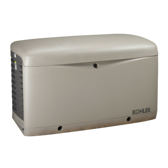
Kohler 14/20RESA Руководство по установке - Страница 21
Просмотреть онлайн или скачать pdf Руководство по установке для Портативный генератор Kohler 14/20RESA. Kohler 14/20RESA 44 страницы. Residential/commercial generator sets

1.8 Electrical Connections
DANGER
Hazardous voltage.
Will cause severe injury or death.
This equipment must be installed and
serviced
by
personnel.
Grounding electrical equipment. Hazardous voltage can
cause severe injury or death. Electrocution is possible
whenever electricity is present. Ensure you comply with all
applicable codes and standards.
generator set, transfer switch, and related equipment and
electrical circuits. Turn off the main circuit breakers of all
power sources before servicing the equipment. Never contact
electrical leads or appliances when standing in water or on wet
ground because these conditions increase the risk of
electrocution.
Electrical backfeed to the utility. Hazardous backfeed
voltage can cause severe injury or death. Install a transfer
switch in standby power installations to prevent the connection
of standby and other sources of power. Electrical backfeed
into a utility electrical system can cause severe injury or death
to utility personnel working on power lines.
NOTICE
Canadian installations only. For standby service connect
the output of the generator set to a suitably rated transfer
switch in accordance with Canadian Electrical Code, Part 1.
Have an authorized distributor/dealer or a licensed
electrician make the following electrical connections.
The electrical installation must comply with the National
Electrical Coder (NEC) class 1 wire designation and all
applicable local codes. Canadian installations must
comply with the Canadian Electrical Code (CEC) and
applicable local codes.
1.8.1
Grounding
Ground the generator set. The grounding method must
comply with NEC and local codes.
grounding strap to the generator set ground lug,
terminal GND inside the controller compartment.
Generator sets are shipped with the generator neutral
bonded (connected) to the generator ground in the
junction box. The requirement for having a bonded
(grounded) neutral or ungrounded neutral is determined
by the type of installation. At installation, the neutral can
be grounded at the generator set or lifted from the
ground stud and isolated if the installation requires an
ungrounded neutral connection at the generator. The
The National Electrical Coder is a registered trademark of the National Fire Protection Association, Inc.
TP-6803 12/11
qualified
electrical
Electrically ground the
Connect the
generator set will operate properly with the neutral either
bonded to ground or isolated from ground at the
generator.
Various regulations and site configurations including the
National Electrical Code (NEC), local codes, and the
type of transfer switch used in the application determine
the grounding of the neutral at the generator. NEC
Section 250 is one example that has a very good
explanation of the neutral grounding requirements for
generators.
1.8.2
Electrical Lead Entry
Drill or punch holes in the enclosure for the electrical
conduit in the locations shown in Figure 1-16.
full-scale dimensioned template for the hole locations is
printed in Appendix B. See page 41.
1
Note: See Appendix B for a full-scale template
with dimensions.
1. 1/2 NPT female fuel inlet
2. ATS signal electrical lead entry point
3. Utility voltage electrical lead entry point
Figure 1-16 Electrical Lead Entry Locations
1.8.3
Field-Connection Terminal Block
The generator set is equipped with a field-connection
terminal block located in the air inlet area near the
junction box. Leads have been factory-installed from
the junction box to the terminal block for easy field
wiring.
See the dimension drawing in Section 1.5 for the
terminal block location. See Figure 1-17 for terminal
block details. Refer to the terminal block decal for
connections and cable sizes. Also see Section 2, Wiring
Diagrams.
A
2
3
ADV--7876
Section 1 Installation
21
