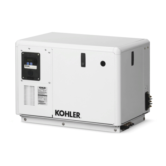
Kohler 5EFKOD Инструкции по установке - Страница 2
Просмотреть онлайн или скачать pdf Инструкции по установке для Портативный генератор Kohler 5EFKOD. Kohler 5EFKOD 4 страницы. Marine with adciid controller
Также для Kohler 5EFKOD: Руководство по установке (13 страниц), Руководство по установке (16 страниц)

Installation
Note: Read all safety precautions at the beginning of
this publication before performing any work on
the generator set.
1.
Remove the generator set from service.
1.1
Press the generator set OFF/RESET button to
shut down the generator set
1.2
Disconnect the generator set engine starting
battery, the negative (--) lead first.
2.
Install the circuit breaker.
2.1
Remove the screws from the right side junction
box panel and remove the panel.
2.2
Install the circuit breaker on the right side of the
junction box. Position the ON side of the circuit
breaker toward the rear of the junction box.
2.3
Single Pole Circuit Breaker Attach the stator
lead marked 1 to the side of the circuit breaker
marked LINE (see Figure 1). Bolt together leads 2
and 3 and tape to insulate them from ground.
Attach the stator lead marked 4 to L0. Attach the
customer load lead connection to the LOAD side
of the circuit breaker.
Two Pole Circuit Breaker Attach the stator leads
(1 and 2) to the LINE side of the circuit breaker and
attach the customer load lead connection to the
LOAD side of the circuit breaker (see Figure 2).
Attach the stator leads marked 3 and 4 to LO.
Three Pole Circuit Breaker Attach the stator
leads (1, 2, and 3) to the LINE side of the circuit
breaker and attach the customer load lead
connection to the LOAD side of the circuit breaker
(see Figure 3). Attach the stator lead marked 4 to
LO.
Note: The neutral (L0) connection is located in
the junction box. See Figure 4.
2.4
If the kit includes cover plate(s) (229183), use the
cover plate(s) to cover any opening. See Figure 7.
3.
Restore the generator set to service.
3.1
Check that the generator set is OFF.
3.2
Reconnect the generator set engine starting
battery, the negative (--) lead last.
2
Stator Leads
3 4 1 2
1
LINE
LOAD
1. Tape to insulate from ground
2. Circuit breaker, single pole
Figure 1 Single Pole Circuit Breaker Connections
Stator Leads
3 4
1 2
LINE
LOAD
Figure 2 Double Pole Circuit Breaker Connections
2
Customer
Load Lead
L0 (NEU)
Customer
Load Lead
Customer
Load Lead
L0 (NEU)
Customer
Load Lead
TT-1696
11/16
