A.H. Systems SAS-542 Руководство по эксплуатации - Страница 6
Просмотреть онлайн или скачать pdf Руководство по эксплуатации для Антенна A.H. Systems SAS-542. A.H. Systems SAS-542 9 страниц. Biconical antenna
Также для A.H. Systems SAS-542: Руководство по эксплуатации (13 страниц)

A.H. Systems AK-4G Antenna Kit
assembly. Connect a cable between the antenna connector and the receiver. The
broadband dipole beam pattern is similar to a dipole response.
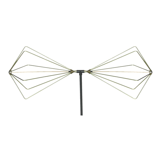
SAS-542 Biconical Antenna 20 MHz - 330 MHz
The biconical antenna consists of the SAS-542 balun assembly and two folding
biconical elements.
Operation: Attach the balun assembly to the tripod thru the screw hole in the
balun assembly base. Screw the two biconical elements into the 'tee' end of the
balun assembly. Open the antenna elements completely and secure in open
position by tightening the knurled knobs in the element caps. Connect a cable
between the antenna connector and the receiver. The biconical beam pattern is
similar to a dipole response.
SAS-550-1B Active Monopole Antenna 10kHz - 60 MHz
The active monopole antenna consists of a ground plane upon which are mounted
a preamplifier with internal rechargeable battery pack for battery operation, and a
telescoping rod antenna.
Operation: Mount the antenna on the tripod. Connect an external ground to the
ground plane if called out in test specification. Attach the telescoping rod to the
connector on the amplifier top and extend fully. Connect the output on amplifier
side to the receiver using a cable. Apply power to antenna (turn battery power 'on'.
The active monopole antenna is omni-directional.
MAGNETIC LOOP ANTENNA
SAS-560 Magnetic Loop Antenna 20 Hz - 2 MHz
The loop antenna does not require any assembly.
Operation: The loop antenna is designed to be held by hand and moved around
each surface if the EUT to measure magnetic radiation. Connect the antenna via a
cable to a receiver with either a 50 ohm input or high impedance (10 K ohm or
greater) input. Calibrations for both inputs are provided.
CURRENT PROBES
BCP-610 LF Current Probe 20 Hz - 20 MHz
BCP-611 HF/VHF Current Probe 10 kHz - 150 MHz
The current probes come ready for use.
Operation: The two current probes measure conducted emissions when clamped
around a single conductor, cable or a bundle of conductors. Disconnect the probe
latch Position the probe around the conductor and close the probe. Reconnect the
probe latch to ensure that the probe is tightly closed. Connect the probe connector
to the receiver with a cable. The probe calibrations supplied are into a 50-ohm
receiver.
© A.H. Systems inc. – May 2014
REV B
6
