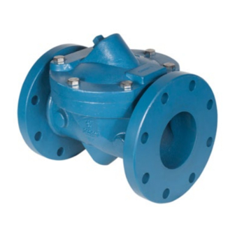
DeZurik APCO CRF-100 Руководство по установке, эксплуатации и техническому обслуживанию - Страница 6
Просмотреть онлайн или скачать pdf Руководство по установке, эксплуатации и техническому обслуживанию для Блок управления DeZurik APCO CRF-100. DeZurik APCO CRF-100 14 страниц. Rubber flapper swing check valves

DeZURIK
APCO CRF Rubber Flapper Swing Check Valves
Maintenance
(Continued)
7. Carefully replace cover over the flapper so as not to move the flapper from its seating position,
then replace cover bolts and tighten lightly while alternating the tightening of each cover bolt
180° apart to prevent tilting the cover.
8.
Slowly open discharge isolation valve to pressurize rubber flapper check valve and observe the
cover gasket (3) joint is not leaking.
Note: Cover Gasket is not used on rubber lined valves.
Operation
The flow from the pump opens the flapper. When the pump is shut off, backflow pressure (and Spring
Assist or Spring Return if equipped) pushes the flapper to close against the body seat surface. If the
valve is equipped with a Bottom Mounted Buffer, as the disc is closing, the flapper closes freely for the
majority of its travel from full open to close. When the flapper is about 90% closed, it comes in contact
with the Buffer Rod (33) which controls the speed of closing for the last 10% of flapper travel. See
Figure 2. This type of control provides for proper adjustment to suit the best performance for the
installation, and can minimize pipeline surge and water hammer.
The bottom mounted buffer assembly (figure 2) utilizes two air over oil tanks, an accumulator (32) and
an oil reservoir (27). The accumulator is pressurized to allow the buffer to fully extend by counteracting
the pressure in the pipeline. The oil reservoir is vented to atmosphere and its main function is to
lubricate the piston and the cylinder.
Start-up Procedure (Bottom Mounted Buffer)
1. Remove the pipe plug from the top of the oil reservoir and replace it with the air breather cap
that is supplied with the valve (it is normally taped to the tank or oil piping).
2. Check for proper oil levels. Make sure both oil tanks are in vertical position.
a. Hydro-pneumatic Tank Accumulator (32) - Release air pressure and remove pipe plug on
the side of the tank. Oil should be visible in the elbow, which is the oil fill level. Add if
necessary. See "Oil Filling Procedure."
b. Oil Reservoir (27) - The oil should be checked when the valve is open. Oil should be
visible in the elbow, which is the oil fill level. Add if necessary. See "Oil Filling Procedure."
3. Make initial adjustments to the following speed controls:
•
Flow Control Valve (41) = 3 turns open. See "Adjustment of Flow Control Valve"
•
Internal Cushion Needle Valve = 1-1/2 turns open. See "Operation of Internal Cushion."
•
Fully open Flow Control Valve (41A) that is connected to the oil reservoir.
4. Pressurize Hydro-pneumatic tank to a pressure according to the formula:
D12007
Tank pressure = Line pressure + 5 psi
4
Page 6
December 2012
