DeZurik G-SERIES Руководство - Страница 8

Просмотреть онлайн или скачать pdf Руководство для Контроллер DeZurik G-SERIES. DeZurik G-SERIES 17 страниц. Lift, turn and reseat used on ptw & pfw tapered plug valves
Также для DeZurik G-SERIES: Инструкция (7 страниц), Руководство (8 страниц), Руководство (14 страниц), Руководство (12 страниц), Руководство (14 страниц), Руководство (16 страниц), Инструкция (19 страниц), Руководство (17 страниц), Руководство по эксплуатации (13 страниц), Руководство (9 страниц)
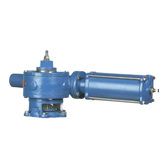
DeZurik G-SERIES Руководство
DeZURIK
Manual G-Series Actuators on PEC Eccentric Valves
Actuator Removal
3. Scribe corresponding lines on the actuator housing and top cover so the cover can be reinstalled in
the correct position.
4. Remove the screws attaching the top cover on the actuator and lift the cover from the housing.
5. If the valve is a size 4" thru 20", remove the lock nut, spring washers and flat washers from the plug
stud and go to Step 9. If the valve is a size 24" thru 36", do not remove anything, go to the next
step.
6. Loosen lockscrew #1 about 6 to 8 turns. Loosen lockscrews #2 about 3 turns. See Figure 3.
7. Using a soft hammer, tap the heads of the #1 lockscrews to loosen the keys.
8. Remove the four screws holding the washer to the gear sector, then remove the stud, locknut,
spring washers and the washer with the keys attached.
9. Remove the 6 screws fastening the adaptor to the valve. On the 4", 5", 6" and 10" valves, these
screws also hold the bonnet to the valve body.
10. Lift the actuator and adaptor off the valve.
11. Scrape the old gasket material from the valve bonnet and the bottom of the adaptor.
12. Scrape the gasket material from the actuator cover and housing.

Non-Submerged Service Actuators

1. Discontinue flow and relieve pipeline pressure.
The valve is a pressure vessel. Pressure must be completely released before
removing the bonnet bolts on the 4", 5", 6" and 10" valves.
2. Scribe corresponding lines on the valve and actuator to be used for alignment during actuator
installation.
3. If the valve is a size 4" thru 20", remove the lock nut, spring washers, wrenching nut and pointer
from the plug stud, then go to Step 7. If the valve is a size 24" thru 36", do not remove anything and
go to the next step.
D10063
(Continued)
Figure 3 – 24" thru 36" Key and Lockscrew Arrangement
Page 8
August 2012