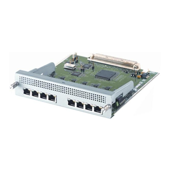
Allied Telesis AT-AR040 Руководство по установке и безопасности - Страница 9
Просмотреть онлайн или скачать pdf Руководство по установке и безопасности для Сетевое оборудование Allied Telesis AT-AR040. Allied Telesis AT-AR040 12 страниц. Network service module
Также для Allied Telesis AT-AR040: Руководство по установке и безопасности (13 страниц)

Installation and Safety Guide
LEDs and What They Mean
AT -AR040 LEDs
The AT-AR040 NSM unit does not have independent LEDs. See
related to NSMs" on page 10
unit switch or router.
AT -AR041 and AT -AR042 LEDs
LED
Active
Data
for information about related LEDs found on the base-
State
Function
Green
Lit when the BRI has successfully completed the
exchange of INFO 1 and INFO 2 signals, and INFO
3 and INFO 4 signals are present on the link. This
means the ISDN interface is correctly connected
to a working NT device.
Off
There is no connection to the ISDN, or the ISDN
has deactivated the connection.
Amber
For on-demand ISDN, lit when there is a call up
over the respective B channel.
For permanent circuits, lit when HDLC packets are
being exchanged between the switch or router and
another TE end system device (normally another
switch or router) over the respective B (data)
channel.
Flashing Amber
For on-demand ISDN, flashing when data is being
exchanged.
Off
For on-demand ISDN, Off when there is no active
connection or when continuous data exchange is
occurring.
For permanent ISDN circuits, Off when no data
exchange is occurring.
9
"Base Unit LEDs
613-000610 Rev A
