Avtech CSD-714 Selcal Руководство по установке - Страница 7
Просмотреть онлайн или скачать pdf Руководство по установке для Медиаконвертер Avtech CSD-714 Selcal. Avtech CSD-714 Selcal 20 страниц.

- 1. Table of Contents
- 2. Description
- 3. Operation
- 4. Specifications
- 5. Installation
- 6. Installation Testing
- 7. Equipment and Accessory Part Numbers
- 8. Notes for Installation Figures
- 9. Figure 1 - Wiring Diagram
- 10. Figure 2 - Outline Drawing
- 11. Figure 3 - Code Programming
- 12. Figure 4 - 20 Db Attenuator
- 13. Figure 5 - Annunciator Output Circuits
CSD-714 Installation and Operation Manual
DESCRIPTION
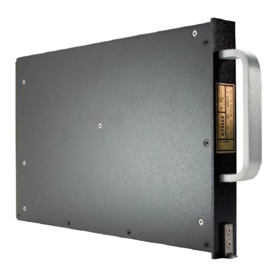
The CSD-714 SELCAL DECODER is a rack mounted, 16 tone decoder for the ICAO and ARINC
standard SELCAL system, as defined in RTCA paper DO-93. It is available in both two channel
(-001, -003) and five channel (-000, -002) versions. It has independent inputs for up to five
radios, depending on version, to drive up to five decoder channels. It is connected to any
communication radio receivers (typically the VHF and HF receivers) and monitors their audio
outputs for the SELCAL tone codes. Upon receiving the code for which it is programmed it will
cause annunciator control line outputs to activate to alert the crew that a call has been received.
TSO'd to TSO C59 and designed to meet or exceed the performance requirements of ARINC
Characteristic 714, the CSD-714 uses proven aircraft techniques and materials and is digitally
based and crystal controlled using a microprocessor, digital filters and signal processing, and
digital frequency generation for its decoding functions. The entire unit is housed in a 1 MCU size
case as defined in ARINC characteristic 600 and is made entirely of aluminum which has been
anodized and painted for protection and appearance. The materials used within the unit are of the
high quality associated with air transport equipment and consideration has been given to the safety
and reliability requirements of air transport operations.
By grounding pins in the rear connector of the unit, either at the connector or by using a code
selector panel, the individual code assigned to the aircraft is programmed for the unit to recognize.
There are several output lines to control the annunciation of a decoded call. Up to five of the lines
are intended to activate lights to indicate which of the inputs received the call, and two of the lines
are used to determine whether the lights will be on steady or flash and to strobe a chime in the
aircraft audio system.
The decoder channels are individually reset by grounding the RESET input pins on the connector.
When all channels have been reset, the steady and interrupted annunciator output lines will be
deactivated. The reset lines are fully diode isolated and may be used with the individual radio
push-to-talk circuits for automatic reset upon transmission.
A Self-Test function is activated by grounding the SELF-TEST input on the connector and will
fully test the unit by generating audio tones internally and coupling them to the inputs of the unit.
1
23-21-01
June 1995
Seattle, WA USA
Rev 1
Page 1
