Dell PowerEdge M910 Техническое руководство - Страница 16

Просмотреть онлайн или скачать pdf Техническое руководство для Сервер Dell PowerEdge M910. Dell PowerEdge M910 49 страниц. M-series blade servers
Также для Dell PowerEdge M910: Руководство по обновлению (44 страниц), Руководство по обновлению (21 страниц), Руководство по обновлению (14 страниц), Руководство по установке (7 страниц), Руководство по обновлению (28 страниц), Руководство по началу работы (12 страниц), Руководство по началу работы (12 страниц), Техническое руководство (46 страниц), Руководство по портфолио (27 страниц), Техническое руководство (45 страниц), Руководство по началу работы (14 страниц), Руководство по началу работы (12 страниц)
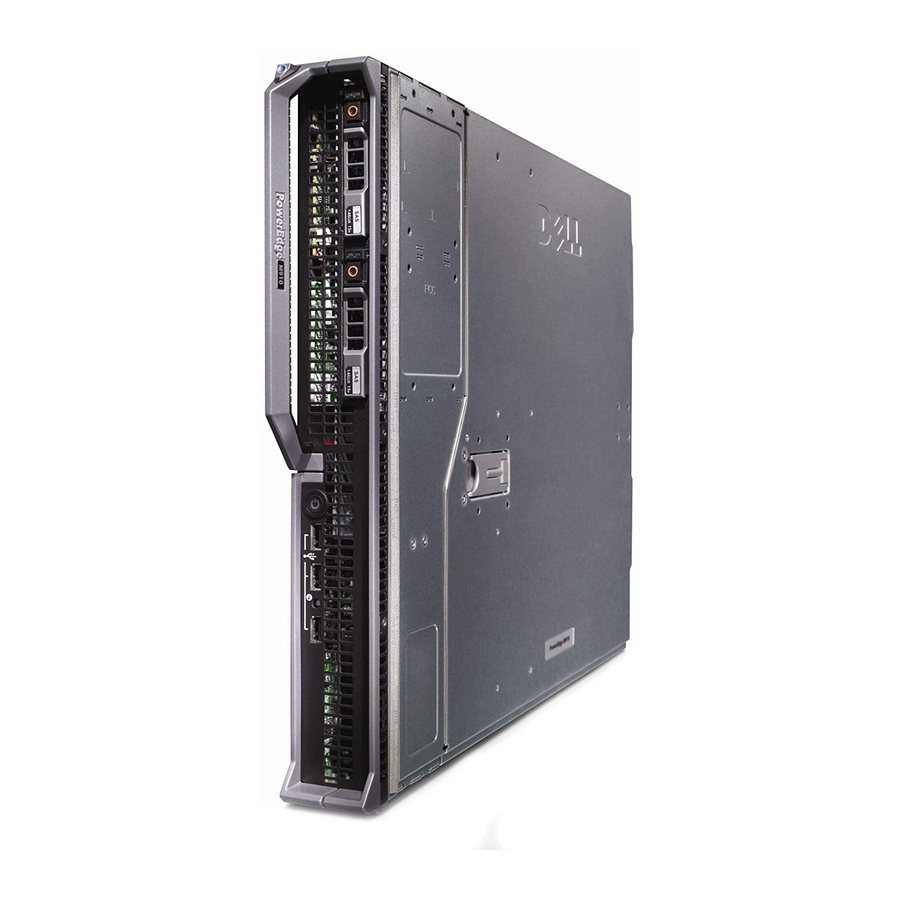
Dell PowerEdge M910 Техническое руководство
Dell

4.4 Back View and Features

Figure 2 shows the back view of the M910.
Figure 2.
Back View
See the Blade Features section in the About Your System chapter of the Dell PowerEdge Modular
Systems Hardware Owner's Manual on
Support.Dell.com/Manuals
for more information.

4.5 Power Supply Indicators

The power supplies must be connected to a power distribution unit (PDU), and not directly to an
electrical outlet. The power supplies require a 200V–240V power source.
See the Power Supply Indicators section in the About Your System chapter of the Dell PowerEdge
Modular Systems Hardware Owner's Manual on
Support.Dell.com/Manuals
for more information.

4.6 LED Indicators

Each disk drive carrier has two LED indicators visible from the front of the system. One is a green LED
for disk activity and the other is a bicolor (green/amber) LED for status information. The activity LED
is driven by the disk drive during normal operation. The bicolor LED is controlled by the SEP device
on the backplane. Both LEDs are used to indicate certain conditions under direction of a storage
controller.
PowerEdge M910 Technical Guide
16