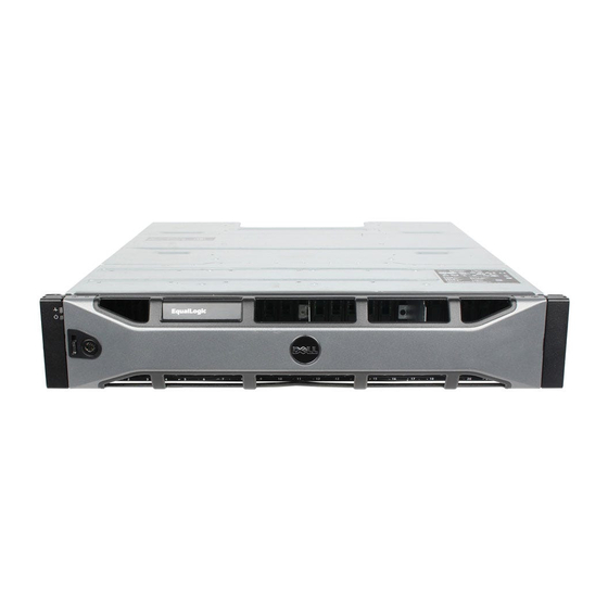
Dell EqualLogic PS Series Обслуживание оборудования - Страница 22
Просмотреть онлайн или скачать pdf Обслуживание оборудования для Хранение Dell EqualLogic PS Series. Dell EqualLogic PS Series 46 страниц. Storage arrays
Также для Dell EqualLogic PS Series: Настройка (2 страниц), Руководство пользователя аппаратного обеспечения (50 страниц), Руководство пользователя аппаратного обеспечения (48 страниц)

PS5000 Hardware Maintenance
Note: This manual shows PS5000 arrays with Type 5 control modules installed.
The information is also applicable to arrays with Type 4 control modules.
See the PS Series Release Notes for the latest supported control modules.
Interpreting Control Module LEDs
Control modules have LEDs that enable you to determine the status of the control
module (active or secondary) and identify problems. In addition, each network
interface on a control module also has LEDs.
Table 3-1: Control Module LED Descriptions
Control Module LEDs
ACT
ERR
PWR
Table 3-2: Network Interface LED Descriptions
Network Interface LEDs Color
Left (as shown in
Figure 3-1)
Right (as shown in
Figure 3-1)
3–2
Figure 3-1: Control Module LEDs
Color
Description
Off
No power, secondary control module is not
synchronized with active control module, or
error condition.
Green
Active control module (serving network I/O).
Orange
Secondary control module; cache is
synchronized with active control module.
Off
No power or no error condition.
Red
Array is starting up or error condition.
Off
No power.
Green
Power.
Description
Off
No power or not connected to network.
Green
Connected to network.
Off
No power or not transmitting.
Green
Transmitting.
Maintaining Control Modules
