Dell SC9000 Руководство пользователя - Страница 8
Просмотреть онлайн или скачать pdf Руководство пользователя для Хранение Dell SC9000. Dell SC9000 18 страниц.
Также для Dell SC9000: Руководство по началу работы (10 страниц)
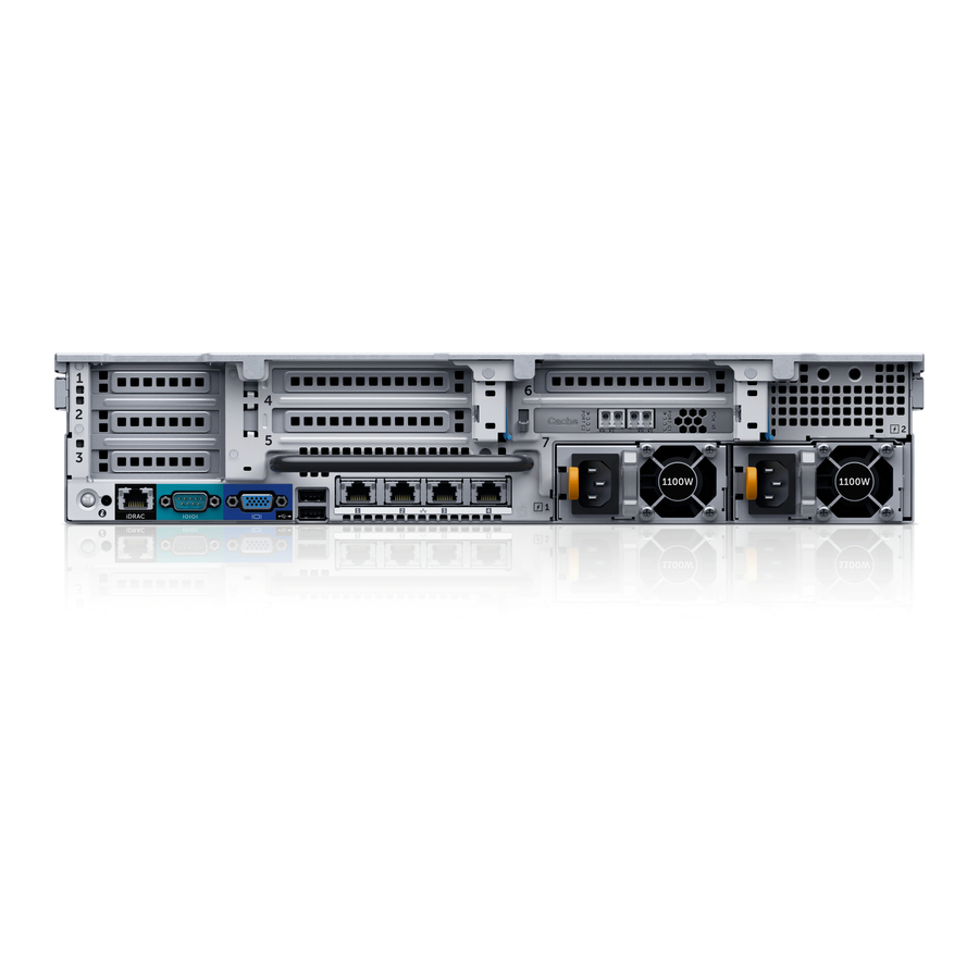
Item
Indicator, button, or
connector
1
System identification
button
2
System identification
connector
3
iDRAC8 Enterprise port
4
Low-profile IO card slots
(3)
5
Serial connector
6
Video connector
7
USB connector (2)
8
Full-height IO card slots
(3)
9
Ethernet connectors
10
Power supply unit (PSU1) ―
11
Cache card
12
Power supply unit
(PSU2)
8
Icon
Description
Used to locate a particular system within a rack.
When a System ID button on the front or back
panel is pressed, the front LCD panel and the back
system status indicator flash until one of the
buttons is pressed again.
•
Press to toggle the system ID on and off.
•
If the system stops responding during POST,
press and hold the system ID button for more
than five seconds to enter BIOS progress mode.
Connects the optional system status indicator
assembly through the optional cable management
arm.
Dedicated management port.
Ports are numbered from left to right.
―
Connects a serial device to the system.
Connects a VGA display to the system.
Connects USB devices to the system. The ports are
USB 3.0-compliant.
Ports are numbered from right to left.
―
Connects the storage controller to the Ethernet
switch and to other storage controllers in the rack.
The ports function as follows:
•
IPC 1: 10Gb (Connect to second storage
controller for IPC).
•
MGMT 0: 1GbE (Connects to the Ethernet
switch for system login, email, alerts, SNMP
traps, diagnostic data, and access for software).
NOTE: IPC 3 and MGMT 2 are not used.
1100 W, 100–240 V AC, autoranging, 50/60 Hz
Improves the performance of the storage system
―
by temporarily storing data before it is written to
disk.
1100 W, 100–240 V AC, autoranging, 50/60 Hz
―
About the SC9000