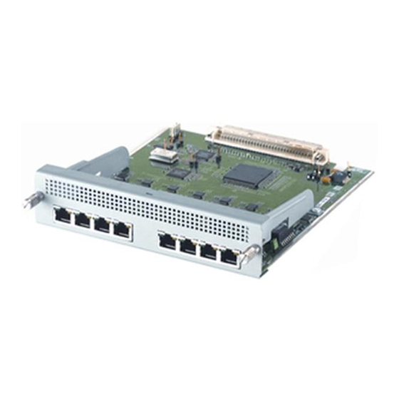
Allied Telesis AT-AR040 Руководство по установке и безопасности - Страница 11
Просмотреть онлайн или скачать pdf Руководство по установке и безопасности для Сетевая карта Allied Telesis AT-AR040. Allied Telesis AT-AR040 13 страниц. Network service module
Также для Allied Telesis AT-AR040: Руководство по установке и безопасности (12 страниц)

10
LEDs and What They Mean
The following LEDs report operations and faults on NSMs:
"AT-AR041 and AT-AR042 LEDs" on page 10
■
"AT-AR048 LEDs" on page 11
■
"Switch and Router LEDs" on page 11
■
The AT-AR040 NSM unit does not have independent LEDs. See
LEDs" on page 11
router.
PIC LED descriptions can be found in the Port Interface Card Hardware Reference,
which can be downloaded from www.alliedtelesis.com/support/software.
AT -AR041 and AT -AR042 LEDs
The following table describes LEDs on the AT-AR041 and AT-AR042 NSMs.
LED
Active
Data
613-000610 Rev B
for information about related LEDs found on the base switch or
State
Function
Green
Lit when the BRI has successfully completed the
exchange of INFO 1 and INFO 2 signals, and INFO
3 and INFO 4 signals are present on the link. This
means the ISDN interface is correctly connected
to a working NT device.
Off
There is no connection to the ISDN, or the ISDN
has deactivated the connection.
Amber
For on-demand ISDN, lit when there is a call up
over the respective B (data) channel.
For permanent circuits, lit when HDLC packets are
being exchanged between the switch or router and
another TE end system device (normally another
switch or router) over the respective B channel.
Flashing Amber
For on-demand ISDN, flashing when data is being
exchanged.
Off
For on-demand ISDN, Off when there is no active
connection or when continuous data exchange is
occurring.
For permanent ISDN circuits, Off when no data
exchange is occurring.
Network Service Module
"Switch and Router
