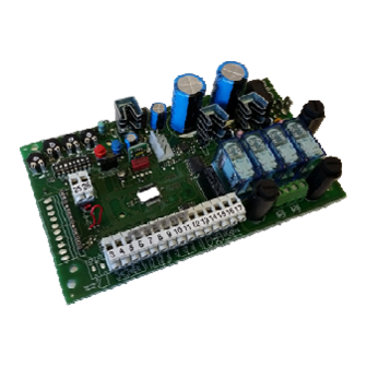
Allmatic AS24 Руководство по установке - Страница 10
Просмотреть онлайн или скачать pdf Руководство по установке для Блок управления Allmatic AS24. Allmatic AS24 10 страниц. Control unit for 1-2 motors 24vdc

19. Additional card (not supplied as standard)
The control unit AS24 has a connector (see diagram on page 1) where it is possible to insert an additional card in order to have the outputs for
connection of the electric lock and the courtesy light. The lighting time of the courtesy light is fixed at 1 minute and 30 seconds. It lights for every
operation of the user.
HOLE TO CONNECT THE SPACER
BETWEEN THE ADDITIONAL CARD
AND THE CONTROL BOX.
20. Second radio channel
In case in which you utilize a radio receiver with card, it is possible to provide the control unit with an output terminal for a second radio channel
(with N.O. contact). Instead, if you want to utilize the radio module present on the card, the second radio channel is not available.
21. Problem solving
This paragraph intends to give some indications for solving the most common problems. Before proceeding, check that the LED present on the
panel are correctly on or off, according to the following diagram:
Step by step
off
If one of more LED are not in the correct status check the corresponding input. In case exclude the external accessories bridging the related
inputs (photocell, stop, limit switch) with the common in case of normally closed contact.
Check the points in the following table:
Type of problem
On activating the open command, the wings do
not move.
On activating the open command, the wings
move for a brief moment and then stop.
On activating the open command, the wings
close.
Impossible to programme remote controls.
It is impossible to enter in wing stroke
programming mode.
During the learning, a wing stop before to reach
the total opening.
On learning phase, le wings arrive on total
opening but the gate does not re-close.
GUARANTEE - In compliance with legislation, the manufacturer's guarantee is valid from the date stamped on the product and is restricted to the
repair or free replacement of the parts accepted by the manufacturer as being defective due to poor quality materials or manufacturing defects.
The guarantee does not cover damage or defects caused by external agents, faulty maintenance, overloading, natural wear and tear, choice of
incorrect product, assembly errors, or any other cause not imputable to the manufacturer. Products that have been misused will not be guaran-
teed or repaired. Printed specifications are only indicative. The manufacturer does not accept any responsibility for range reductions or malfunc-
tions caused by environmental interference. The manufacturer's responsibility for damage caused to persons resulting from accidents of any na-
ture caused by our defective products, are only those responsibilities that come under Italian law.
6-1622372
rev.5 04/02/2016
1
2
LC
Vac/dc
Pedestrian setting
stop
or clock
off
on
Loss of electrical power.
Burned fuse
Incorrect encoder connection
Motor cables inverted
The type of decoding set in the control
panel does not correspond to the type of
remote control used.
The gate is not closed
RUNNING AMP.SENS. Trimmer threshold
too low
RUNNING AMP.SENS. Trimmer threshold
too high
ITA
CONNECTOR TO BE INSTALLED IN
THE CONTROL UNIT.
TERMINALS 1 & 2: Output for courtesylight. Timed for 90 SEC.
TERMINALS 3 & 4: Output for electrical lock. Timed for 3 SEC.
CLEAN CONTACTS WITHOUT VOLTAGE
3
4
Max load 220 V - 5 A
ELS
Vac/dc
LED STATUS
External
Internal
photocell
photocell
on
on
possible cause
ENG
FRA
ESP
DEU
POR
Limit switch
Limit switch
Wing 1
Wing 2
on
on
Solution
Check the presence of electrical power and all
the connections of the electrical network.
Replace the fuse with one with the same
characteristics
Check encoder wiring
Check motor wiring, inverting them if necessary.
Check which decoding was set and select the
one which corresponds to the remote controls in
use.
Close (in manual) the gate. If the gate was
closed, set the SW1 selector to manual mode,
wait 1 second and put it back into automatic
mode. Try again to enter into setting mode.
Increase the intervention value of the ampere
sensor.
Decrease the intervention value of the ampere
sensor.
Pag 10 di 10
