Miller 3001 SYSTEM AIR Руководство по эксплуатации - Страница 3
Просмотреть онлайн или скачать pdf Руководство по эксплуатации для Аксессуары для фотоаппаратов Miller 3001 SYSTEM AIR. Miller 3001 SYSTEM AIR 8 страниц. Fluid head + tripod
ENGLISH
Introduction
Thank you for purchasing the Miller System AIR. The Miller System AIR is a professional standard camera support product that
offers stability, accuracy and durability. The robust design and construction of the full fluid movement supported by precision ball
bearings and quality finishes for long lasting performance.
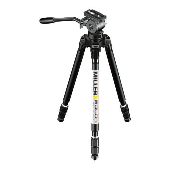
System AIR Operations - Solo tripod setup
q
Select rubber foot position for either indoor or outdoor conditions.
Indoor (hard surfaces): rotate anticlockwise all rubber feet (check foot is fully down).
Outdoor: rotate clockwise all rubber feet fully to expose spike.
Adjust pan handle to position required by loosen clamp and adjust to desired angle then tighten clamp.
w e
Whilst holding tripod system and with leg angle in position No. 1 loosen the 1st stage leg locks and adjust to desired
length and tighten. If more height is required loosen 2nd stage leg locks to desired length and tighten. When using leg angle
position No. 2 only use 1st stage leg locks to adjust to desired height and for leg angle position No. 3 keep tripod leg fully collapsed
for ultra low ground hugging heights.
AIR fluid head Setup
r t
To level fluid head loosen ball level clamp nut and keep bubble inside bullseye of bubble level and tighten clamp nut.
y u i
To mount the camera apply pan / tilt locks and loosen slide lock screw and pull camera plate whilst pressing
grey release knob. Fix the camera plate to the camera using the appropriate screw, spare screws can be stored under the camera
platform. With camera and plate attached insert assembly into rear of camera platform until release knob engages the camera
plate into the platform. Slide the camera position over the tilt axis of the fluid head to approximate balanced location and tighten
slide lock screw.
o a
With counterbalance selected in position 1 release tilt lock whilst holding pan handle and allow it to tilt back or forward
to see if the camera is balanced. Loosen slide lock screw and slide camera and plate in the appropriate direction for a better
balanced position then tighten slide lock screw and recheck camera balance again. If camera is balanced but still falls backwards
and forwards the select position 2 of counterbalance.
Maintenance
s
Use spanner to adjust leg pivot tension.
Options
d
The optional 2092 Accessory mounting block 1/4" can be fixed to side of head by using 4 mm hex key. This 1/4" can then be
used for mounting accessory viewfinders. Ball level stud (13 mm) can be removed so head can be mounted to 3/8" screw flat base
applications.
Storage and transport
Loosen pan / tilt locks also pan handle and clamp and adjust to side position. Whilst holding tripod system loosen leg locks and
adjust 1st and 2nd stages to full collapsed position and tie legs together using transport strap and snap buckle.
Optional Accessories
2092 Accessory mounting block 1/4"
682 Pan handle & clamp (2nd)
1520 Solo shoulder strap
394 Solo Dolly
EN