Burkhard Reuter RLA4 Технические характеристики и руководство по эксплуатации - Страница 5
Просмотреть онлайн или скачать pdf Технические характеристики и руководство по эксплуатации для Антенна Burkhard Reuter RLA4. Burkhard Reuter RLA4 9 страниц.

This results in an omnidirectional reception without pronounced main receiving direction or suppression in
one direction. In addition, the reception power is highly dependent on the installation of the antenna. A high
installation location as well as a large distance to conductive and / or noise emitting parts should be
chosen. In whip mode, the antenna easily picks up local noise. It is also more sensitive to overvoltages
(e.g. static discharge when touching the receiving loops or nearby transmitters). Always touch the housing
or other grounded conductive parts in the vicinity before touching the loop construction!
The antenna is not protected against direct lightning and must not be operated in lightning-prone
environments!
Caution! The switch consists of only a small operating lever made of plastic and may only be used
cautiously! Do not use forces greater than necessary for direct switching!
In operation, the lever lights red in loop mode and green in whip mode. When switched off, there is no
display and the power consumption is completely zero.
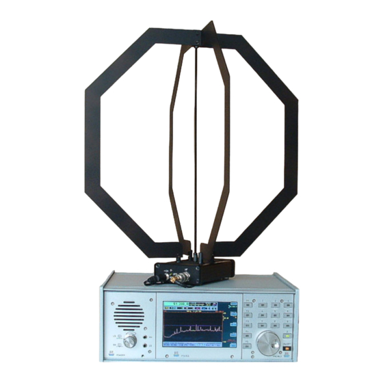
The antenna elements (loops) are easy to disassemble. Each loop consists of 2 sections assembled to the
amplifier with one screw and two screws to the common mounting and grounding point. After removing the
screws with a suitable screwdriver, the element is removable. The center rod can be turned out after
loosening the lock nut on the housing. When the receiving elements are removed , the antenna can be
packaged and transported to save space.
Caution! During assembly work on the antenna, torque must never be transferred to the 5 connection
bolts of the amplifier! This can damage the inner PCB! Always keep the bolts firmly in its correct position,
e.g. with a suitable nut key!
Versions for loop constructions
The RLA4 is available in 3 basic versions (extended versions see below):
- RLA4A: Normal version with 2-layer black coated loop material.
- RLA4B: "Blue version" with 4-layer blue coated loop material.
- RLA4C: Special version with loops made of flexible stainless steel.
In version B, the outer layers of the loops are connected to ground and only the inner layers carry power to
the amplifiers. This results in an additional shielding of the receiving loops against interference voltages.
Depending on the environment and on the reception frequency an increased attenuation can be achieved.
Version C includes spring steel loops. They are attached by knurled nuts, which allows a quick
disassembly and assembly. This allows the antenna to be transported space-saving. In addition, the loop
straps are very robust and rustproof, so that the RLA4C is well suited for portable use (housing is not
completely waterproof). The stainless steel bands offer up to approx. 10 MHz the same receiving power as
the copper loops of the RLA4A and B, only above the performance drops slightly.
In whip operation, the material of the loops is irrelevant. All versions give the same reception performance.
Remote supply / direction control
The previous description refers to the supply of the antenna directly to the housing with 12 V DC. The
RLA4 can also be supplied with operating voltage via the RF cable (remote supply). The local supply via
the DC socket should then be removed. The switch is no longer active and doesn't light up, even if the
antenna is receiving power via the remote power supply!
Caution! The antenna should always be supplied via a well-stabilized, interference-free power supply
("analogue" or "linearly controlled"). This is especially true for the local supply via the DC socket.
For remote supply, various methods for controlling the antenna are available (applies to versions A to C):
•
Supply with > 8 V (observe permissible maximum!): The RLA4 operates in loop mode.
•
Supply with <= 8V (observe the required minimum!): The RLA4 operates in whip mode.
•
Supply with 6 V and modulation of an RS-232 signal with active level of min. 7 V and
maximum 8 V: Control of the RLA4 in all available operating modes.
EDITION
DATE
1.5
8/19/19
K & M Burkhard Reuter
NAME
RLA4
B. Reuter
5
9
Page
of
