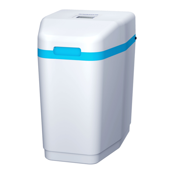
AQUAPHOR S550 P1 Руководство по эксплуатации - Страница 9
Просмотреть онлайн или скачать pdf Руководство по эксплуатации для Диспенсер для воды AQUAPHOR S550 P1. AQUAPHOR S550 P1 20 страниц.

Sewerage
The unit drain must be routed to a waste water outlet,
such as a drain or washing machine drain, in accordance
with all local and national plumbing codes. An air gap or
siphon must be provided to prevent backflow (see the
"Installation and commissioning step by step" section).
Power supply
The power supply is designed for mains voltage of
220 VAC with a frequency of 50 Hz. If there is a possibil-
ity of voltage deviation from the specified values by more
than 5–10 %, use a voltage stabilizer. This will prevent
malfunctions and failure of both the power supply and the
electronic components of the softener.
ATTENTION! It is not recommended to separately con-
nect the softener to uninterruptible power supplies, as
this may cause failures in the regeneration process-
es. Connection is only possible in conjunction with
a pumping station.
If you have any questions, please contact support. For
support information, see the General Information section
and the warranty card.
Step-by-step
instructions for
installing a softener
The softener connection must be made in accordance
with local plumbing codes.
The connection, setup and operation of the device must be
carried out within the limits of operation specified in this
manual. Failure to follow these guidelines may reduce flush-
ing efficiency and result in softener malfunction or failure.
How to do:
• The softener must be installed after the hydraulic
accumulator tank and pump control automation sys-
tems.
• The softener must be installed in front of the water
heater and other appliances that consume water.
• The softener must be installed at least 1 m from heat-
ing appliances.
• It is not recommended to install the softener on
a heated floor, as this may cause excessive evapora-
tion from the brine tank and fouling of the softener
surfaces with salt crystals.
• Water for watering a lawn or garden does not require
softening and filtration, so this water can be drained
before the softener.
• When connecting the softener, it is recommended to
provide a bypass valve - "bypass" (see fig. 5). The by-
pass valve will simplify the maintenance of the soften-
er and will provide the supply of unsoftened water in
case of emergency when the softener is dismantled.
It is also recommended to drain the first portions of
contaminated water through the bypass after mainte-
nance work on the well, water supply or pump.
• If the length of the pipe between the softener and the
water heater is less than 3m, it is recommended to
install a non-return valve on this line as close as pos-
sible to the water heater. Make sure the water heater
is set to the correct temperature and the safety valve
is correct and in good working order.
You cannot do:
• Install and operate the softener in a room where the
temperature can drop below +5 °C.
• Install and operate the softener in a room with humid-
ity over 70 %.
• Install the softener near heating appliances.
• Connect the softener to the water supply in the op-
posite direction.
Step 1. Prepare a place for connection
• Turn off the power and water supply to the water
heater. For gas water heaters, additionally turn the
gas valve to the "Maintenance" or "Off" position. (See
instructions for your water heater).
• Turn off the water supply. Open hot and cold water
taps to relieve pressure in the lines. Check the water
supply for lime deposits, rust or other contaminants.
Clean or replace clogged plumbing.
• Organize the insertion point of the softener, according
to fig. 3 so as to prevent axial distortions and tensions
during installation, as this can lead to damage to the
bypass assembly or softener valve.
• Arrange an electrical outlet at a distance of no more
than 2 m.
NOTE: The bore diameter of the pipe from the accumula-
tor tank to the softener must be at least 3/4".
Step 2: Connect the softener to the water supply
The softener must be connected to the water line in ac-
cordance with national and local building, plumbing, and
electrical codes.
• Remove the softener lid, to do this, first remove the
front lid by grasping the cutout in its front part, then
remove the lid by pulling it up and towards the front
of the softener housing.
• Empty the salt compartment from all packaging and
installation materials.
• Make sure that the shims are inserted into the union
nuts of the flexible hoses. Connect the softener to the
water supply using flexible hoses.
9
