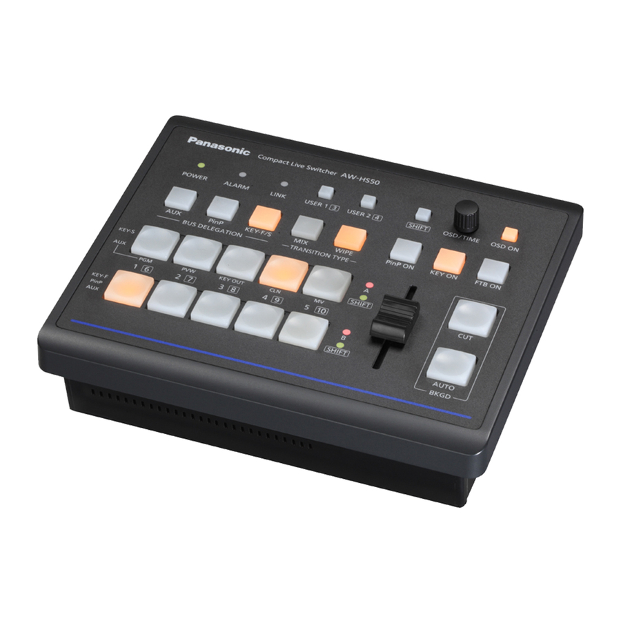
Panasonic AW-HS50 Series Краткое руководство по эксплуатации - Страница 2
Просмотреть онлайн или скачать pdf Краткое руководство по эксплуатации для Цифровая камера Panasonic AW-HS50 Series. Panasonic AW-HS50 Series 4 страницы. Combining pinp
Также для Panasonic AW-HS50 Series: Руководство (20 страниц), Брошюра и технические характеристики (4 страниц), Руководство (4 страниц), Руководство (2 страниц), Краткое руководство по эксплуатации (6 страниц)

To crosspoint buttons 1 – 10, external video input signals, internally generated signals, etc. can be assigned as a
source.
Crosspoint Button
1 to 10
SDI-IN1 to SDI‐IN4
DVI-IN
FMEM1, FMEM2
CBGD
CBAR
Black
NoAsign
※Video signals will not be switched even if a button is pressed where "NoAssign" is assigned.
■ Settings for Output
This switcher can output signals from the three connectors: SDI OUT1, SDI OUT2 and DVI-D OUT.
The output signals are set on the menu: [11] Output Menu – (Figure 3).
(Figure 3: Menu Screen for [11] Output Menu *factory default)
The output systems can individually be assigned the following signals.
PGM
PVW
CLN
AUX
MV
KEY OUT
※ For MV (Multi View Display), please see the following manual "AW-HS50 – Multi View Display".
https://eww.pass.panasonic.co.jp/pro-av/support/content/faq/EN/remcam/17_.pdf
■ "No image output"
・ Does the signal format of the switcher match that of the input source?
If AW-HS50 switcher receives an input signal that is different from its system format, a black screen or distorted
image is displayed.
Please check if the switcher's system format (see below for the menu) matches that of the input source.
※ AW-HS50 Menu : [14]SYSTEM Menu > 1.Format
(Supported formats: 1080/59.94i, 1080/50i, 720/59.94p, 720/50i, 1080/24PsF, 1080/23.98PsF, 480/59.94i, 576/50i)
Source Name
Images inputted into SDI-IN1 to 4
Image inputted into DVI-IN
Images stored in the switcher
Signal outputted from the switcher's built-in color generator
Switcher's internal color-bar signal
Switcher's internally generated signal (black signal)
No signal assigned
This is the main line output.
Images with wipe, mix, key, PinP or other effects added are outputted.
PVW images which enable the next operation to be checked are outputted.
Clean signals (images resulting when the key and PinP effects have been
removed from the PGM signal) are outputted.
The signal selected using the AUX bus is outputted.
Multi view display signal is outputted.
Key signal is outputted.
★ Need help? Troubleshooting ★
Source
