Dickson SM320 Руководство - Страница 2
Просмотреть онлайн или скачать pdf Руководство для Регистраторы данных Dickson SM320. Dickson SM320 4 страницы. Temperature & temperature/ humidity data loggers
Также для Dickson SM320: Начало работы (4 страниц)

1.800.561.8187
Useful Features
Real Time Monitoring
Monitor and graph your process as it happens and print
and save from real time screen. (This feature should
be used sparingly as it causes the battery to drain very
quickly unless using optional AC adapter)
Customize Graphed Data
DicksonWare™ calculates Min, Max and Average
of all data collected. Customize data by eliminating
unnecessary data points and customize Min, Max and
Average to show only desired information.
Logger Operating Instructions
Note: The loggers have a continuous display that cannot
be disabled. Dual variable models such as the TM320/
TM325 and SM325 will toggle between Temperature and
Humidity or two Temperature readings automatically. The
SM320/325 models will read PROB on the display if the
Thermocouple is not connected.
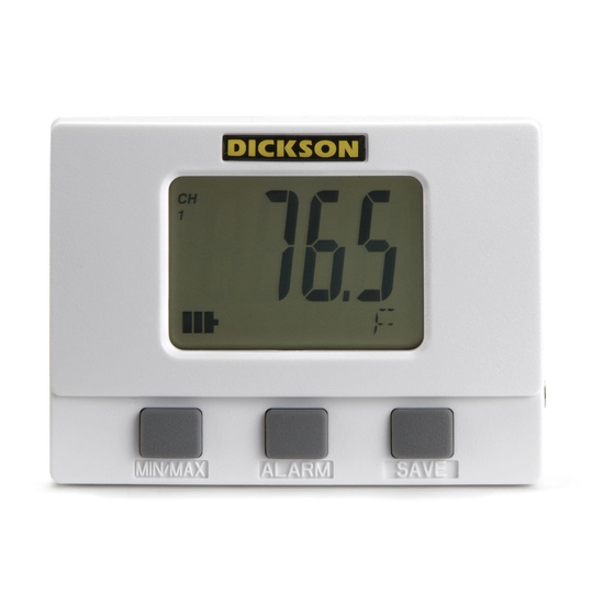
Button Functions:
Save
Note: This feature is only for use with the Dickson
Memory Cards.
Pressing this button will download any data stored in
the logger to the removeable memory card. STORE will
appear on the display momentarily and the counter will
start counting down from 100. DO NOT remove the
memory card until STORE is no longer in the display and
the unit is displaying current readings.
Note: Leaving the memory card installed in the Logger
will reduce battery life by 50%. If you notice "Err" on the
display, please refer to the Trouble Shooting section of
this manual.
Alarm
Pressing this button will silence the alarm. Holding this
button down for about 5 secounds will toggle between
Fahrenheit and Celsius. (Alarm parameters can only
be set in DicksonWare™. Refer to the DicksonWare™
software manual.)
Basic Software & Logger Operating Instructions
SETUP
Click this button first to establish communication
between your Logger and DicksonWare™ software.
You will be prompted to select a USB or Serial COM Port
connection, then click Continue. A Setup window will
appear with ALL fields populated, this confirms that the
software has recognized the logger. Should all fields
remain blank and communication is not established, refer
to the Troubleshooting section of this manual. There are
three tabs within the Setup window:
www.
Export Data
A snapshot of your graph or a real-time graph of points
can be easily exported to other programs such as Excel™
or PowerPoint™.
Super Size Storage
With the use of the optional Flash Memory Card and
reader you can store 100 Full Data Loggers. This elimi-
nates the need to physically remove your loggers from
their application for uninterrupted monitoring.
** CLICK ON THE FEATURES BUTTON IN THE **
SOFTWARE FOR DETAILED INSTRUCTIONS ON
HOW TO USE ABOVE FEATURES
MIN/MAX
Pressing this button will start the Min/Max display cycle.
Clearing MIN/MAX Values
Holding the "MIN/MAX" and "ALARM" buttons down
together until "clr" appears on display will clear the
stored minimum and maximum values. The Min and
Max displayed by the logger will be the minimum and
maximum values sensed since it was last cleared.
Note: DicksonWare™ will show the minimum and
maximum values of the downloaded data. These could
be different than that displayed on the unit itself.
For Example: Your logger is set for a 2 minute sample
which is good for about 11 days. After 5 days you clear
MIN/MAX. After another 6 days you download the
logger. The Min/Max displayed by the logger will be the
MIN/MAX for the last 6 days. The MIN/MAX shown by
DicksonWare™ will be the Min/Max for the last entire
11 days. Dew point MIN/MAX in the TM320 and TM325
models are not updated unless dew point is enabled
using DicksonWare™ software.
Battery Replacement
To replace the batteries (4 "AA" alkaline) remove the
screw on the back of the case.
Installing a Flash Memory Card Reader
Follow the instructions included with the flash card
reader. Additional information and trouble shooting
information on the card reader can be found at that
manufacturers website.
Identification
Provides you with the Model and Serial number of the
logger as well as the option to set a custom User Id by
clicking the active Setup to the right of the User Id field.
Samples
Majority of the setup process takes place in this section.
Each field with an active Setup button to the right is a
parameter that you can customize. Sample Interval is for
telling your logger how frequently you want it to take
.com
