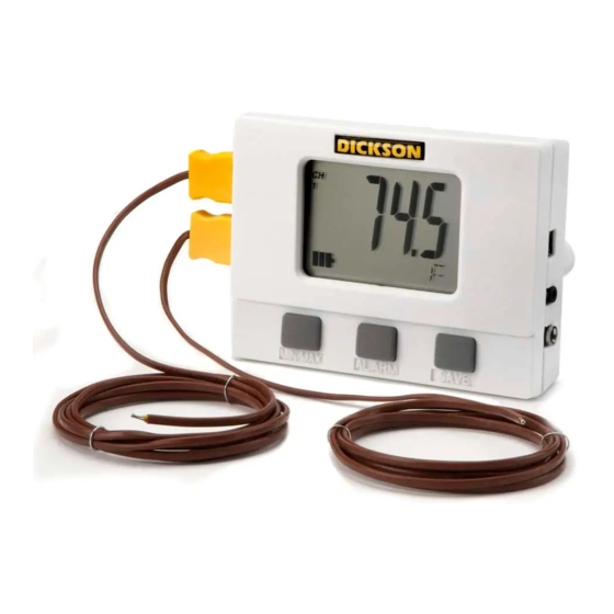
Dickson VFC320 Веб-руководство - Страница 4
Просмотреть онлайн или скачать pdf Веб-руководство для Регистраторы данных Dickson VFC320. Dickson VFC320 11 страниц. Vaccine display loggers operation

Getting Started
To setup the VFC320 or VFC325 you'll need to be at your PC.
1.
Insert Batteries: Included in the shipping box are 4AA batteries. Remove the battery door on the
back of the unit using a Phillips screwdriver. Insert the 4AA batteries and replace the battery door.
2.
Position velcro on the back of the unit for mounting.
3.
K-thermoucouple beadwire probe(s) are connected to the unit
4.
Installing DicksonWare™ Software: Make sure the PC is running Windows 98 or higher
DicksonWare™ Version 10.0.8 or higher is needed to operate this VaccineData Logger. If you currently
have DicksonWare™ on the PC, check the version. Choose Help on the Menu Bar. Choose About. The
version is shown in the dialog box.
To install and start DicksonWare™ Software onto your PC, insert the CD into the CD drive.
Follow the steps on the screen. Once installed a DicksonWare™ icon appears on the desktop.
5.
Connect one end of the USB cable to the logger and the other cable end to the PC.
Press the MIN/MAX button to toggle between Fahrenheit and Celsius on the display
6.
7.
Double click the DicksonWare™ icon. A dialog box appears to register the software. Click on one
of the options. Follow these steps to setup the logger:
Across the top menu bar, choose File, Preferences. Click on Fahrenheit or Celsius for down
a.
loaded data temperature readings. Then choose OK.
Click the Setup button located in the upper left hand corner of the software window. This
b.
establishes communication between the Logger and DicksonWare software.
A dialogue box appears. Select USB or Serial depending on the type of download cable. Click
c.
CONTINUE.
8.
A setup window pops up with five tabs. The Identification tab is chosen. All fields should be
automatically filled in. The Model number, Serial number, Calibration Date and Factory Calibration
Date are identified. This confirms that DicksonWare has recognized the logger.
Factory Calibration date identifies when the unit was calibrated. Calibration Date identifies when
the next calibration is needed. Should all fields remain blank, refer to "No Communication" in the
Troubleshooting section of this manual.
9.
In the setup window, choose the Samples tab.
a.
No changes can be made to the Start Date/Time, sample interval or stop or wrap when full
section.
b.
Samples per Channel tells you how many samples of data have been collected and the logger
capacity that has been used.
c.
Log Time identifies how much time the chosen sample rate will cover to fill the logger.
d.
Battery Level shows the amount of battery life available. To achieve longer battery life during
operation, use a less frequent sample rate, disconnect the unit from the USB port when not
downloading data, limit the frequency of memory card transfers and DO NOT insert the memory
card all of the way into the logger unless downloading.
10.
In the setup window, choose the Channels tab. Each unit has two channels. The temperatures shown
here are real-time readings. No changes need to be made.
11.
Setup the Min/Max Alarm conditions
a.
In the setup window, choose the Ch1 Temp Alarm Tab to set the Min and Max alarm conditions
for Channel 1. Ch1 is the external probe for the VFC320 and top probe for the VFC325.
b.
In the setup window, choose the Ch2 Temp Alarm Ch2 is the internal sensor for the VFC320 and
the bottom probe for the VFC325. The factory preset alarm temperature parameters are shown
To change these temperatures, just type in another Minimum temperature and/or Maximum
temperature.
Rev. 10/07
