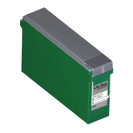
Alpha Group OutBack Power EnergyCell 200PLC Руководство пользователя - Страница 11
Просмотреть онлайн или скачать pdf Руководство пользователя для Аксессуары для фотоаппаратов Alpha Group OutBack Power EnergyCell 200PLC. Alpha Group OutBack Power EnergyCell 200PLC 20 страниц.

To make the DC connections:
Make certain to clean all terminals and contact
surfaces according to the steps on page 10.
1. If installing batteries in a rack or cabinet,
always begin with the lowest shelf for
stability. Place all batteries with terminals
facing to the most accessible side of the
rack. If terminal protectors are present,
remove and save them.
2. In common configurations, the battery
on one end will be the positive (+) output
for that string. This battery should be
designated [1]. Proceeding to the other
end, adjacent batteries in that string
should be designated [2], [3], and so on.
3. If more than one string is present, designate the first string as A, the second as B, and so on.
This should be done regardless of whether the strings are on the same shelf or higher shelves.
Number the batteries in subsequent strings just as in step 2.
4. Install series connections. If an interconnecting bar was supplied, it should connect from
the negative (left) side of battery [1] to the positive (right) side of battery [2] as shown above
(see arrow). Top-terminal batteries require short interconnecting cables to be provided.
Tighten interconnect hardware "hand tight" only.
5. Repeat the process as appropriate for batteries [2], [3], and any others in the string. Connect
the proper number of batteries in series for the nominal voltage of the load.
6. If multiple series strings will be used, repeat this process for strings B, C, and so on.
7. Install parallel connections. Parallel connections are made from the positive terminal of
one battery or string to the positive of the next; negative connections are made similarly.
(See Figure 4 on page 9.) External cables or bus bars must be provided. Interconnecting
bars cannot make parallel connections.
8. Use a digital voltmeter (DVM) to confirm the nominal system voltage and polarity. Confirm that
no batteries or strings are installed in reverse polarity.
9. Install cables or bus bars for DC loads. Size all conductors as appropriate for the total loads.
See the manual for the battery rack or cabinet if necessary.
10. Before making the final battery connection, ensure the main DC disconnect is turned off.
If this is not possible, then do not make the final connection within the battery enclosure.
Instead, make it at the load or elsewhere in the cable system so that any resulting spark
does not occur in the battery enclosure.
11. Once hardware is installed and batteries are properly aligned, torque all connections to the
appropriate value for the battery model. (See the requirements on page 19.) Lightly coat the
surfaces with battery terminal grease. Reinstall the terminal covers if present.
IMPORTANT:
Before using the battery bank, commission the batteries as described on the next page.
900-0227-01-00 Rev A
Figure 7
EnergyCell Batteries
Interconnecting Bar
Connecting Batteries
11
