Axis Industries SDU-1M Техническое описание, инструкция по эксплуатации - Страница 3
Просмотреть онлайн или скачать pdf Техническое описание, инструкция по эксплуатации для Аксессуары Axis Industries SDU-1M. Axis Industries SDU-1M 12 страниц. Ultrasonic flow sensor

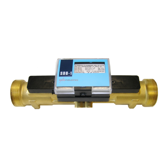
Ultrasonic flow sensor SDU-1M is designed as sub-assembly of heat meter. SDU-1M is used
for measuring fluid flow rate in heating systems and conversion it into electrical pulse signal.
As a component of heat energy meter the SDU-1M flow sensor could by used for commercial
account of energy quantity in district heating plants, in factories, in single or multi family houses.
SDU-1M corresponds to essential requirements of the Technical Regulation for Measuring
Instruments, dated 30 March 2006 (transposing in the NB's country law Directive 2004/22/EC of 31
March 2004 on measuring instruments):
- Annex I
- Annex MI-004
SDU-1M meets the requirements according to accuracy class 2 of EN1434.
SDU-1M meets the requirements according environmental class C of EN1434-1.
Ambient temperature:
Mechanical environment class:
Electromagnetic environment class:
Type reference example for technical documentation and order placing:
Sensor SDU-1-M
Type , modification
3
Permanent flow rate, m
Value of pulse, l/pulse
Battery:
0 – without battery/ 1 – with internal battery
Pulse cable (length):
01 – 3 m; 02 – 5 m; 03 – 10 m; 04 – 15 m; 05 – 20 m
06 – 40 m; 07 – 60 m; 08 – 80 m; 09 – 100 m; 10 – 125 m
11 – 150 m; 12 – 175 m; 13 – 200 m; 00 – none
Remark: * - marked numbers are used only for order coding.
2.1.
The measured parameter is a fluid volume that is converted into normalized pulse sequence.
2.2.
Table of the flow sensors flow rates, lengths, connection thread (flanges) and the pressure
losses ∆P
at q =q
:
,
p
Permanent
Length, mm
flow rate,
q
p
3,5
260
6,0
260
10,0
300
15,0
270
25,0
300
40,0
350
60,0
350
2.3.
Flow measurement threshold 0,2 q
2.4.
Admissible measuring error according to EN1434 (class 2):
PESDU1M02 (MID)
1. APPLICATION
Essential requirements
Heat meter ,
- 10
/h
2. TECHNICAL DATA
Connection
Thread G 1 1/4
Thread G 1 1/4
Thread G 2
Flange DN50
Flange DN65
Flange DN80
Flange DN100
i
= ± (2+0,02q
E
/q)
f
p
o
5 ...55
C
M1
E2
- 0,05
- 0*
- 01*
Limits of flow rate,
lower
permanent
q
q
i
p
0,035
3,5
0,06
6,0
0,1
10,0
0,15
15,0
0,25
25,0
0,4
40,0
0,6
60,0
3
Pressure losses
m
/h
∆
p, at q
upper
p,
MPa,
q
s
less than
7,0
0,004
12,0
0,01
20,0
0,01
30,0
0,012
50,0
0,02
80,0
0,018
120,0
0,018
Fig. No.
A
appendix
Fig. A1
Fig. A1
Fig. A2
Fig. A3
Fig. A4
Fig. A4
Fig. A4
3
