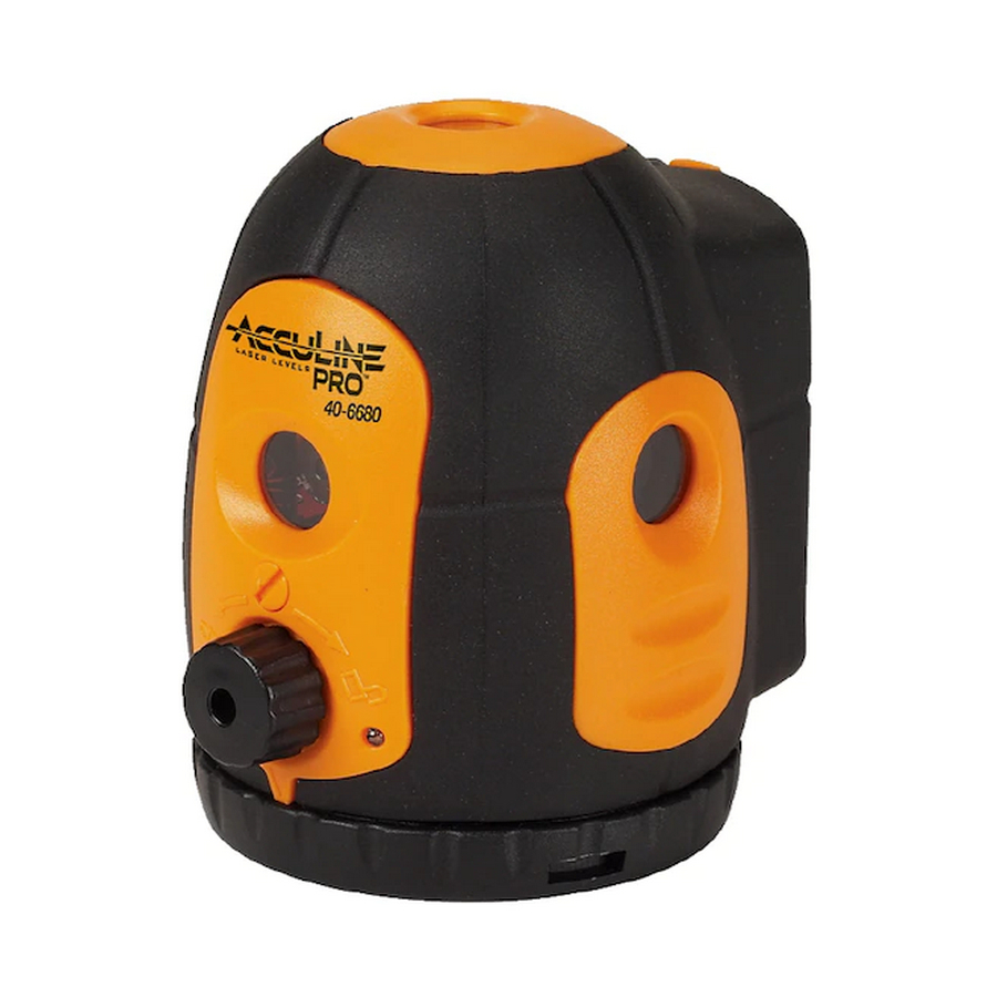
AccuLine 40-6680 Руководство по эксплуатации - Страница 5
Просмотреть онлайн или скачать pdf Руководство по эксплуатации для Лазерный уровень AccuLine 40-6680. AccuLine 40-6680 16 страниц. 5 beam laser pointer
Также для AccuLine 40-6680: Руководство по эксплуатации (13 страниц)

5.
Using a Phillips screwdriver, remove 3 cross-slot plate screws M2×12
(5-6-4#) and remove gimbal module (5-6-5).
6.
Using a 3M Hex Wrench, remove the inner hexagon tightening screw
M3×3 (5-6-7)
7.
Using a 3/32" steel rod, remove off the pendulum module (5-6-6#) by
turning it counterclockwise (while looking at it from the bottom).
Reference see figure 10.
8.
Using a soldering iron, de-solder all connection lines between the laser
modules and the connecting board (eight pieces in all). Screw off two
cross-slot plate screws M2×4(5-6-8#) by a cross screwdriver. Take off
the connecting board module (5-6-9#);
9.
Using a Phillips screwdriver, remove 4 cross-slot plate screws
M2×8(5-6-10), and remove the prism module (5-6-11).
10. Using a Phillips screwdriver, remove 4 cross-slot plate
screws M2×8(5-6-12), then remove 3 laser source
modules 1 respectively (5-6-13);
11.
Using a Phillips screwdriver, remove 4 cross-slot plate
screws M2×8(5-6-14), then remove laser source
module2 (5-6-15). Reference see figure 11.
Prepared By: Tim Wojo
5- 6- 9
5- 6- 11
5- 6- 13
Revision - Date: 0 – 20080430
40-6680 Service Manual
5- 6- 4
5- 6- 5
5- 6- 6
5- 6- 8
5- 6- 10
5- 6- 15
5- 6- 12
5- 6- 7
Figure 10
5- 6- 14
Figure 11
Page 5 of 16
