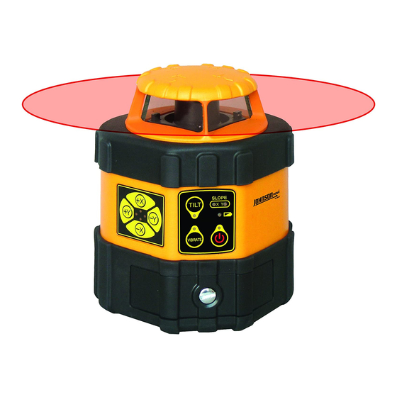
AccuLine 40-6537 Руководство по эксплуатации - Страница 11
Просмотреть онлайн или скачать pdf Руководство по эксплуатации для Измерительные приборы AccuLine 40-6537. AccuLine 40-6537 15 страниц. Auto-leveling rotating laser
Также для AccuLine 40-6537: Руководство по эксплуатации (18 страниц)

Coarse Adjust - Calibration via Internal Leveling Sensors
If the error is more than ±0.5mm/m, it will need to make calibration by adjusting the sensor. The details are as follows:
Reference point
Wall
Sensor module (2pcs)
Crosshead plate screw M2×5 (4pcs)
Fixture Setup (See Above)
1. Fix a square reflected prism on the debugging platform, and affix a label paper that having a light-emitting
aperture in center on the prism (the diameter of the aperture is about 1mm). Put an auto-leveling rotating laser that
having plumb-up point on the platform. Power on the unit and the plumb-up point will pass through the prism and
the light-emitting aperture of the label paper, and then to reflect on the wall. Take the center of the reflected laser
point on the wall as a point A.
2. Turn the unit by 90°, and take the center of the laser spot on the wall as points B, C, D in turn. The center of
internally tangent circle of these four points A, B, C, D is used as the reference point.
Core Module/Leveling Sensor Calibration
1. Fix the core part on the special clamp. By supplying the laser source with a power of DC 3V,
pass through the aperture on the laser paper
tribrach base (shown above), in order to make the center of the reflected laser spot coincident with the reference
point.
2. Fix the sensors of X & Y direction to the proper positions on the core part using 2 crosshead plate screw M2×5.
3. Adjust the position of the sensors by connecting a specially designed instrument developed for sensor levelling
position, and adjusting until the signal shows that sensor is level, i.e. the upper & lower arrows occupy no more
than one grid. And then tighten the screws on leveling sensor, securing it to the core module.
4. After the sensors of both X & Y directions have been calibrated, loc-tight the heads of the tightening screws to the
sensors so that they cannot come loose.
Prepared By: Tim Wojo
Reflected prism
10m
Label paper with a 1mm round aperture in center
Connecting plate
Adjustable tribrach base
Fixture used for adjusting the sensor
and to reflect on the wall. Adjust the three leveling knob on the
Revision - Date: 0 – 03232009
40-6537 Service Manual
Display of the adjusting fixture for sensor
Display of the well-adjusted sensor
the laser spot will
Page 11 of 15
