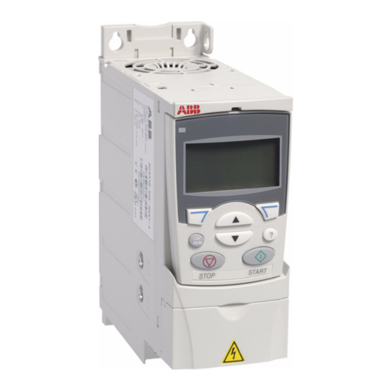
ABB ACS320 series Дополнительное руководство - Страница 14
Просмотреть онлайн или скачать pdf Дополнительное руководство для Контроллер ABB ACS320 series. ABB ACS320 series 16 страниц. Variable frequency drives in renewaire ventilators
Также для ABB ACS320 series: Инструкции по установке (4 страниц), Инструкции по установке (4 страниц)

OPERATION
SETTINGS
14
RENEWAIRE.COM
ABB VFD SUPPLEMENTAL MANUAL
ABB VARIABLE FREQUENCY DRIVES
DANGER OF MOTOR OVERLOAD LEADING TO SMOKE AND FIRE!
Do not change PARAMETER 2003 MAX CURRENT from RenewAire default setting, which should be set
to no more than 125% of the motor nameplate FLA for motors with 1.15 Service Factor (SF) or higher
or 115% of the motor FLA for motors with less than 1.15 SF and otherwise unprotected. This parameter
controls the Motor OVERLOAD PROTECTION provided by the VFD.
SCALING AND RESPONSE TO ANALOG INPUTS
The most likely reason to control the VFD from
an analog signal is to automatically change the
amount of outside air ventilation to meet the actual
needs for each time period.
If one or both of the VFDs will be controlled by an
analog input from an external Control Device (e.g. a
CO2 controller or a Building Management System),
you may need to "scale" the rate of response of the
VFD(s) to the rate of change of the analog signal.
SCHEMATIC RELATIONSHIP EXAMPLE BETWEEN MEASUREMENT BY A CONTROLLER, THE ANALOG
F9
SIGNAL FROM THE CONTROLLER, THE VFD SCALING PARAMETERS AND THE MOTOR SPEED
(VFD OPERATING FREQUENCIES).
1105 "REF1 MAX"
1104 "REF1 MIN"
1301 MINIMUM AI1
in this example = 55%"
1302 MAXIMUM AI1
in this example = 91%"
ANALOG SIGNAL FROM
CONTROLLER
MEASURED CONDITION
(CO
CONCENTRATION IN THIS EXAMPLE)
2
1.800.627.4499
WARNING
We need to introduce two concepts relating to the
amount of outside air ventilation needed in the building:
• The "ACTION LEVEL" is the level of measurement
of indoor air quality or occupancy at which
the ERV should start to deliver more than the
"Design Minimum Supply Airfl ow";
• The "MAXIMUM RESPONSE LEVEL" is the level of
measurement of indoor air quality or occupancy
at which the ERV should be operating at the
"Design Maximum Supply Airfl ow".
60hz
50hz
40hz
30hz
20hz
10hz
0hz
0vdc
0
4mA
0
500
ACTION LEVEL
MAXIMUM RESPONSE LEVEL
LEVEL AT MAXIMUM DEVICE OUTPUT
10vdc
20mA
1000
1500
2000
