ABB ACS355 series Дополнительное руководство - Страница 5

Просмотреть онлайн или скачать pdf Дополнительное руководство для Контроллер ABB ACS355 series. ABB ACS355 series 16 страниц. Variable frequency drives in renewaire ventilators
Также для ABB ACS355 series: Дополнительное руководство (20 страниц), Руководство по быстрой установке и вводу в эксплуатацию (2 страниц), Руководство по быстрой установке и вводу в эксплуатацию (2 страниц), Инструкции по установке (4 страниц), Руководство по быстрой установке и вводу в эксплуатацию (4 страниц), Инструкции по установке (4 страниц)
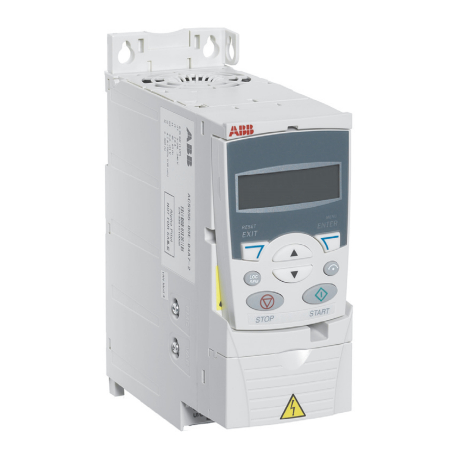
ABB ACS355 series Дополнительное руководство
"ON" SIGNAL CONNECTIONS
If the ERV is equipped with Damper(s) and/or with just one VFD, the ON Signal control wires are connected
to the low-voltage terminal strip in the ERV E-box. See Fig. 1.
Install a jumper between terminals 2 and 3 to use the ERV's on-board 24VAC power. Do this when the
external control(s) have isolated contacts that don't provide any voltage, as in the top two examples.
Make no connections between terminals 1 & 2 and terminals 3-5 if the external control has a voltage
output to provide the ON signal. This voltage must be 24VAC.
With ERVs equipped with no dampers and 2 VFDs, the ON signal control wires are connected directly to the
VFD. See Fig. 2 & 3.
"SPEED" SIGNAL CONNECTIONS
Any SPEED Signal connections are made directly to the VFD (see Figures 4,6 & 7). The VFDs can accept
4-20mA or 0-10vdc analog control signals to operate at varying speeds. The VFDs also can accept
momentary-contact inputs to operate at up to three pre-set speeds. VFD Parameters must be properly set
to accept and act on Speed signals. Wiring for analog control signals should be twisted-pair, single- or
double-shielded cable, with shield (and drain if provided) grounded at only one end of the cable.
LEADER-FOLLOWER CONNECTIONS
ON and SPEED signals can be passed from the LEADER VFD to a FOLLOWER VFD. See Figures 3 & 5.
F1
CONNECTION OF ON SIGNALS TO LOW-VOLTAGE TERMINAL STRIP IN ERV E-BOX.
ABB VARIABLE FREQUENCY DRIVES
1.800.627.4499
INSTALLATION
WIRING OPTIONS
CAUTION
Capacitors in VFDs
Retain Charge
Allow 2 minutes after shutting
off power to the VFDs to allow
the capacitors in the VFD to
fully discharge. Do not connect
or disconnect wires at the VFD
without waiting 2 minutes.
WIRING SCHEMATICS
ABB VFD SUPPLEMENTAL MANUAL
RENEWAIRE.COM
5