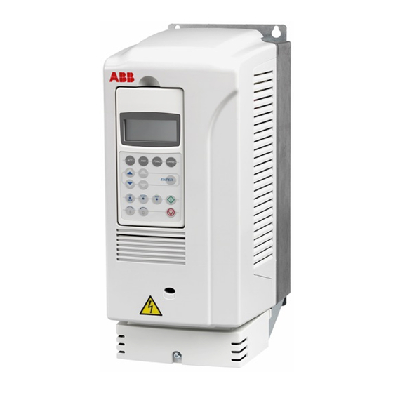
ABB ACS850-04 series Руководство - Страница 6
Просмотреть онлайн или скачать pdf Руководство для Контроллер ABB ACS850-04 series. ABB ACS850-04 series 16 страниц. Converter modules with electrolytic dc capacitors in the dc link
Также для ABB ACS850-04 series: Руководство по быстрой установке (16 страниц)

6 Introduction
•
ACQ580-01, -04, -31 and -34
•
ACS580-01 and -04
•
ACS880-01, -04, -11, -31, -14, -34 and -104.
ABB wind turbine converters
This manual applies to line-side converter modules and generator-side converter modules
in product series ACS800-67LC, ACS800-77LC, ACS800-87LC and ACS800N-87LC.
Note: ACS800-67 and ACS800-77 modules include film capacitors in the DC link instead
of electrolytic capacitors.The film capacitors do not need to be reformed.
ABB solar inverters
This manual applies to solar inverter modules in product series PVS800-57 and PVS800-
57B.
Target audience
You are expected to know the standard electrical wiring practices, electronic components,
and electrical schematic symbols.
Purpose of the manual
The manual provides information needed for reforming the converter module capacitors.
Safety instructions
WARNING! Obey the safety instructions delivered with the converter and given in
this manual. If you ignore them, injury or death, or damage to the equipment can
occur. If you are not a qualified electrical professional, do not do electrical
installation or maintenance work.
1. Drives: Never work on the converter, motor cable or motor when input power is
applied. After you have disconnected the input power, always wait for 5 minutes to let
the intermediate circuit capacitors to discharge before you start to work on the
converter, the motor or motor cable.
Wind turbine converters: Never work on the converter or generator when input power
is applied. After you have disconnected the input power, always wait for 10 minutes to
let the intermediate circuit capacitors discharge before you start to work on the
converter, generator or generator cable.
Solar inverters: Do not do work on the photovoltaic generator or the inverter or its input
or output cables when the inverter is connected to an electrical power system or to the
photovoltaic generator. After you have disconnected the inverter, always wait for 5
minutes to let the intermediate circuit capacitors discharge before you continue.
2. Measure that the installation is de-energized.
•
Use a multimeter with an impedance of at least 1 Mohm.
•
Make sure that the voltage between the converter input power terminals (U1, V1
and W1) and the grounding terminal (PE) is close to 0 V.
•
Make sure that the voltage between the drive DC terminals (UDC+ and UDC-) and
the grounding terminal (PE) is close to 0 V.
3. Never switch on the converter power supply while the reforming circuit is connected.
Lock the disconnector (if any) to an open position.
