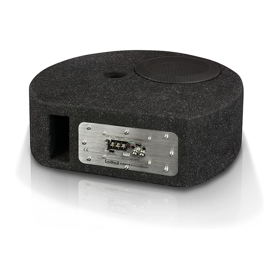
AXTON ATB20STP Руководство по установке и эксплуатации - Страница 4
Просмотреть онлайн или скачать pdf Руководство по установке и эксплуатации для Сабвуфер AXTON ATB20STP. AXTON ATB20STP 12 страниц. 8"/20 cm active subwoofer

MOUNTING & CONNECTIONS
Add a main fuse holder with appropriate fuse volume to the (+) power cable
in a distance of not more than 30 cm from the positive battery pole.
Note that the amp-module generates heat, so a well ventilated mounting place
n
is necessary or it will easily overheat.
Keep the wire connections as short as possible, with sufficient length, in order to
n
minimize power losses and provide a higher audio output of the system.
To minimize damage to the cables, take care that they do not pass through sharp
n
edged metal. Use rubber grommets were required.
Lay all cables as far away as possible from the ignition cables, modules in the boot
n
and under the dashboard, as these create interference.
Keep the length of the power cable as short as possible.
n
The power cable should have at least a cable cross section of 10mm
n
AWG). Smaller cross sections are reducing the output power, are causing
distortions and may be triggering the overheat protection of the amp-module.
(8 Gauge
2
– 6 –
WIRING & CONNECTIONS
IMPORTANT:
Before any wiring, always remove the negative terminal of the battery to
prevent short-circuiting. This is also the last lead to be (re-)connected.
Connect this lead only after having completed and checked all other connections. The battery
terminal (+12V) must be connected directly to the positive terminal of the vehicle battery to
provide an adequate voltage source and minimize noise. Connect it to the terminal of the bat-
tery after all other wiring is completed.
GROUND CONNECTION
The ground terminal (GND) connection is also critical to the correct operation of the ampli-
fier. Use a wire of the same gauge as the +12V cable and connect it between the ground
terminal (GND) of the amplifier and a metal part of the vehicle close to the mounting location.
This wire should be as short as possible and any paint or rust at the grounding point should
be scraped away to provide a clean metal surface to which the end of the ground wire can
be screwed or bolted.
REMOTE TURN-ON CONNECTION
The amplifier is turned on by applying +12V to the remote turn-on terminal (REM). The wire
lead to this terminal should be connected to the „Amp remote" lead from the car stereo which
will provide the +12V only when the car stereo is turned on.
INPUT CONNECTIONS
This amplifier features both high level and low-level (RCA) input capability. Use either the
low-level or high-level inputs, not both. If the car stereo does not provide low-level outputs,
the amplifier may be connected via the speaker (high-level) outputs from the car stereo. Wire
the speaker leads from the car stereo to the 4-pin adaptor harness as shown in the diagram
(shielded cables are not required for this application) and plug the connector into the high
input connector on the amplifier.
Note:
When using the high-level input of your OE factory radiothat features no
dedicated REM signal, select "Auto turn-on" ON.
– 7 –
