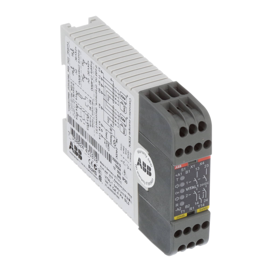
ABB Jocab Safety Vital 2 Руководство - Страница 14
Просмотреть онлайн или скачать pdf Руководство для Контроллер ABB Jocab Safety Vital 2. ABB Jocab Safety Vital 2 14 страниц. Safety controller
Также для ABB Jocab Safety Vital 2: Инструкция по эксплуатации (11 страниц)

Technical data – Vital 3
Manufacturer
Article number/
Ordering data
Vital 3
Level of safety
EN ISO 13849-1
EN 62061
IEC/EN 61508-1...7
EN 954-1
PFH
D
Relay output
Transistor output
Colour
Weight
Power supply
Fuse
An external fuse must be
connected in series with the
supply voltage to A1
Max line resistance
at nominal voltage to X1
Power consumption
Total current consumption
Input function 1
(two channel, normally
closed circuit)
Dynamic output signal
Dynamic input signal
Static input signal (+24 V)
Input function 2
(dynamic safety circuit)
Dynamic output signal
Dynamic input signal
Reset input X1/X11
Voltage at X1/X11 when reset
Reset current
Minimum contact closure time
for reset
Number of sensors
Max. number of Eden or Tina
units per input function 2
Total max. cable length
(depending on the number of
Eden/Tina units)
Max. number of light beams
(Spot T/R) per input function 2
Spot 10
Spot 35
Total max. cable length
(depending on the number of
Spot T/R)
Maximum number of units varies depending on the installation
andcable size. For more information, see the examples in this
chapter.
Response time
Relay output (Q1, Q11)
Safe transistor outputs
(Q2, Q12)
Non-safe transistor output
(Q2, Q12)
ABB
ABB AB/Jokab Safety, Sweden
2TLA020070R4400
PL e, category 4
SIL 3
SIL 3
Category 4
-9
2,00×10
1,50×10
-9
Grey
390 g
24 VDC ±15%
6 A
150 Ohm
300 mA
T1
S1
S2
T11
R11 (odd number of sensors in
a circuit)
R12 (even number of sensors
in a circuit)
+24VDC
30 mA (300 mA peak during
contact closure)
80 ms
10
500 m
1
3
100 m
15 – 24 ms
11 – 20 ms
11 – 20 ms
Relay outputs
Number of outputs
Max. load capacity, res. load
Max. load capacity, ind. load
Safe transistor outputs
Number of outputs
Output voltage (rated)
Output voltage (at load)
Max. load
Short circuit protection
Output – 0V
Output – +24V
Non-safe transistor output
(information)
Output voltage (rated)
Max. load
Mounting
DIN rail
Operating temperature
range
Connection blocks
(detachable)
Max screw torque
Max connection area:
Solid conductors
Conductor with socket
contact
Air and creep distance
Protection class
Enclosure
Connection blocks
Approved standards
Connector blocks are detachable
(without cables having to be disconnected)
2 NO
6A/250 VAC
AC-1: 250 V/1,5 A
AC-15: 250 V/1,5 A
DC-1: 50 V/1,5 A
DC-13: 24 V/1,5 A
2
–24V
> 22V at 800 mA/24V
supply voltage
23,3V at 150 mA/24V
supply voltage
800 mA
Yes
Normal (not guaranteed)
+24 VDC
1 A
35 mm DIN rail
-10°C to + 55°C
1 Nm
1x4 mm
2
/2x1,5 mm
2
/12AWG
1x2,5 mm
2
/2x1 mm
2
4kV/2 DIN VDE 0110
IP 40 IEC 60529
IP 20 IEC 60529
EN ISO 13849-1/EN 954-1,
EN ISO 13849-2, EN 62061,
EN 61496-1, EN 574,
EN 692, EN 60204-1,
EN 50178, EN 61000-6-2,
EN 61000-6-4, EN 61000-4-,
IEC/EN 61508-1...7
1
2
3
4
5
6
7
8
9
10
11
12
13
14
5:19
