ABB PDP32.0 Руководство - Страница 12
Просмотреть онлайн или скачать pdf Руководство для Контроллер ABB PDP32.0. ABB PDP32.0 18 страниц. Profibus dp communication module

P D P 3 2 . 0 M A N U A L
—
Diagnosis
Diagnosis and behavior in case of error
The PROFIBUS module provides detailed diagnosis information about the status of the connected device, its own status and
the status of the PROFIBUS connection. Diagnosis information is shown with the locally available lamps and via the standard
PROFIBUS services.
Local Diagnosis PDP32
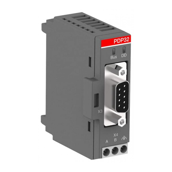
Diagnosis information is locally shown with LEDs (Light Emitting Diodes) Bus and DD located on the front side of the
PROFIBUS module. The meaning of the LED status is as follows:
LED Bus (red, green)
Off
Green flashing
Red flashing
Red
Green
Amber flashing
PROFIBUS Diagnosis
• Standard Diagnosis: The format of the standard diagnosis data is defined within the PROFIBUS standards (IEC 61158). It
consists of 6 octets that cannot be influenced by the field device manufacturer. The diagnosis information is related to the
communication layer and covers run-up diagnosis scenarios such as the device identification, communication mode infor-
mation (FREEZE, SYNC), readiness, availabilities, watchdogs, parameterization and configuration faults.
For details, see IEC 61158-6, 6.2.3.1 to 6.2.3.5. Bit 7 in octet 3 (the "Ext_Diag_Overfl ow" flag) is used by the PROFIBUS com-
munication interface to indicate more diagnosis information then fits into the actual diagnosis message length.
• Extended Diagnosis: PROFIBUS module offers extended diagnosis to make the diagnosis data of the connected devices
available to the PROFIBUS master. Depending on the selected diagnosis format DP-V1 or DP-V0, the content of the diagno-
sis is slightly different. The extended diagnosis telegram has the following format:
Byte in the extended
diagnosis telegram
0
1
2
3
4
5
6
7
8
9
10
11
12
LED DD (red, green)
Off
Amber flashing
Green flashing
Green
Red flashing
Red
Meaning DP-V0
Block length: 10 = 10 Bytes
Communication status communication
interface - UMC:
Value(0) ="Communication OK"
Value(1) ="Lost Communication to UMC100"
Diagnosis Byte 0 UMC (see UMC manual)
Diagnosis Byte 1 UMC (see UMC manual)
Diagnosis Byte 2 UMC (see UMC manual)
Diagnosis Byte 3 UMC (see UMC manual)
Diagnosis Byte 4 UMC (see UMC manual)
Diagnosis Byte 5 UMC (see UMC manual)
Diagnosis Byte 6 UMC (see UMC manual)
Diagnosis Byte 7 UMC (see UMC manual)
-
-
-
Meaning
Power Supply missing
- Connection to master missing
- Bus address of UMC different form the one configured in the
master
- I/O size mismatch between device and master
Parameter mismatch between device and master
Communication lost, supervision timeout time exceeded
OK, normal data exchange
Initializing
Waiting for communication from UMC
OK, normal data exchange
Connection to UMC lost
Internal fault. Replace communication interface.
Meaning DP-V1
Block length: 13 = 13 Bytes
Status type (always 0x81 = Status Mode)
Slot number (always zero)
Status specifi er (always zero)
Communication status communication interface - UMC:
Value(0) ="Communication OK"
Value(1) ="Lost Communication to UMC100"
Diagnosis Byte 0 UMC (see UMC manual)
Diagnosis Byte 1 UMC (see UMC manual)
Diagnosis Byte 2 UMC (see UMC manual)
Diagnosis Byte 3 UMC (see UMC manual)
Diagnosis Byte 4 UMC (see UMC manual)
Diagnosis Byte 5 UMC (see UMC manual)
Diagnosis Byte 6 UMC (see UMC manual)
Diagnosis Byte 7 UMC (see UMC manual)
12
