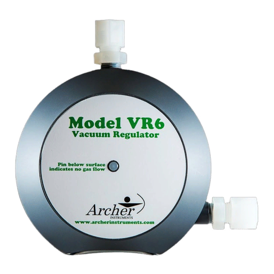
Archer VR6 Установка, эксплуатация и обслуживание - Страница 3
Просмотреть онлайн или скачать pdf Установка, эксплуатация и обслуживание для Контроллер Archer VR6. Archer VR6 5 страниц. Vacuum regulator

Operating the VR6 Vacuum Regulator:
1) Prior to placing the vacuum regulator into operation, it is important to carefully test the
lead gasket seal. A small squeeze bottle (provided with every Archer vacuum regulator)
should be partially filled with ammonia. Squeezing the bottle allows the ammonia fumes to
be used to test for chlorine leaks. A leak is detected by a visible light gray / white gas cloud
when the two fumes interact. To test for leaks, open the cylinder valve 1/3 turn and then
close immediately. This pressurizes the lead gasket seal but ensures the full cylinder of
chlorine is isolated during leak testing. Use ammonia fumes around the cylinder valve and
lead gasket to check for any signs of leaking gas. If a leak is found, this must be addressed
before placing the unit into operation.
2) After confirming no leaks exist, open the chlorine cylinder valve 1/3 of a turn. This is fully
open and there is no need to open the valve further.
3) If the remote meter is not mounted on the VR6, no further action is needed.
4) If the remote meter is installed on the VR6, adjust the remote meter's rate valve knob
until the desired feed rate is indicated on the graduated meter tube.
Maintaining the VR6:
Recommended Maintenance Frequency: Archer recommends yearly routine maintenance.
-Refer to the parts diagram when performing maintenance on the VR6.
1) To disassemble, remove the two yoke screws and pull the metal yoke & inlet assembly
out of the back of the vacuum regulator.
2) Remove the four body screws and separate the front and back bodies. The diaphragm
assembly can then be removed by carefully pulling it straight out of the front body. Take
care to not lose the vent spring, which is located between the diaphragm assembly and the
front body.
3) The guide pin is threaded into the rear diaphragm plate and should not need to be
removed during routine maintenance.
4) The rear diaphragm plate and front diaphragm plate are threaded together and can often
be unscrewed by hand. If they will not unscrew by hand, it may be necessary to use a vice
and / or channel locks. Unscrewing these two parts allows for the removal of the diaphragm.
5) Whenever routine maintenance is being performed, all parts should be thoroughly
