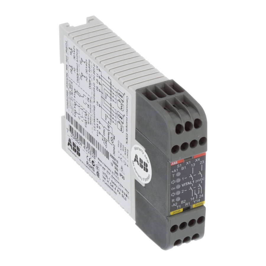
ABB vital 1 Оригинальное руководство по эксплуатации - Страница 15
Просмотреть онлайн или скачать pdf Оригинальное руководство по эксплуатации для Контроллер ABB vital 1. ABB vital 1 20 страниц. Safety controller
Также для ABB vital 1: Руководство (14 страниц)

4
Installation and maintenance
Installation precautions
First mount the unit to a 35 mm DIN rail, then install all cables to the terminals of the
connection blocks (use max. tightening torque 1 Nm).
NB: Do not forget the S1 terminal if an even number of sensors are used (refer to Output
connections above).
Warning! All the safety functions must be tested before starting up the system.
Precautions when using safety light beam Spot with Vital 1:
The information output switch on Vital 1 must be in position 2. A yellow indication lamp must be connected
to the information output and mounted where it is visible from the protected area. Refer to section Output
connections for further details.
Vital 1 must be installed within an electrical cabinet (or similar housing) with a minimum protection class
rating of IP54.
The information output signal from Spot must be connected to an indication lamp in such a way that it:
-
Lights green when Spot is OK (uninterrupted)
-
Lights red when Spot is interrupted
Maintenance
Warning!
The safety functions and the mechanics shall be tested regularly, at least once every year to confirm that all the
safety functions are working properly (EN 62061:2005).
In case of breakdown or damage to the product, contact the nearest ABB JOKAB Safety Service Office or reseller.
Do not try to repair the product yourself since it may accidentally cause permanent damage to the product,
impairing the safety of the device which in turn could lead to serious injury to personnel.
Testing of the safety functions
Make sure the safety unit is working properly by following these steps:
Control that the safety loop is working. The T (transmitter) LED should be turned ON.
When all sensors are active and Vital 1 is reset, the R (receiver) and output relay LEDs should be turned
ON.
When the safety loop is interrupted the R (receiver) and output relay LEDs should turn OFF.
Warning! When Vital 1 has been inactive for an extended period of time (e.g. an extended machine downtime due
to maintenance), the safety function(s) of each safety sensor on the dynamic safety circuit connected to Vital
should be tested before restarting the system.
Troubleshooting
LED indication
Expected causes of faults
Safety loop interrupted, no dynamic signal
-R LED turned OFF
S1 configured incorrectly
-ON LED flashing
Input voltage below 18 V
-R LED flashing
Defected dynamic signal input to unit (asymmetric pulses)
Warning! Replace a defect unit with a new one and never bypass the safety circuit.
2TLC172156M0201, rev. C
2016-07-04
Checking and measures to take
Check if and why there is no dynamic signal
Configure S1 according to "Output connections" above.
Fix power supply
Check the dynamic input or the unit before
15
www.abb.com/jokabsafety
