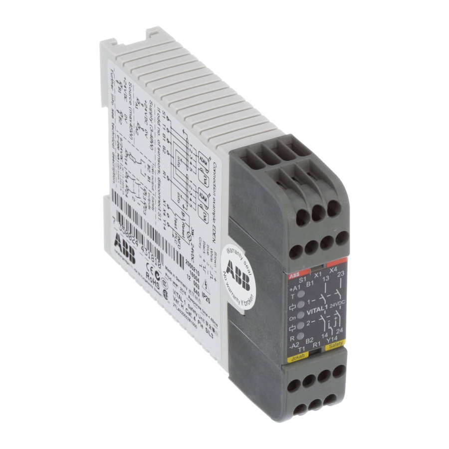
ABB vital 1 Руководство - Страница 9
Просмотреть онлайн или скачать pdf Руководство для Контроллер ABB vital 1. ABB vital 1 14 страниц. Safety controller
Также для ABB vital 1: Оригинальное руководство по эксплуатации (20 страниц)

Connection of protection/sensors - Vital 2
Depending on the input function and the
number of sensors connected to the safety
circuit
(odd or even number), the dynamic
signal is connected between different ter-
minals;
Connection of outputs - Vital 2
Connection of safe transistor output
(-24 V)
The safe transistor outputs Q2 (output
group 1) and Q12 (output group 2) have
an output voltage of -24 V.
Connection of reset - Vital 2
There are two separate reset functions; Re-
set 1 and Reset 2. The function of these is
dependent on the operating mode selected
(see Selection of operating mode). Reset 1
and Reset 2 can be configured for manual
or automatic reset independently of each
other by means of the input's Auto reset 1
and Auto reset 2.
Time delay - Vital 2
Output group 2 can have disconnection delay by connecting inputs 0.5s and 1.0s being connected to +24 V. The system is binary, which
means that the time values of the inputs are added together to give the total delay time.
No delay
5:14
Input function 1:
A dynamic signal is transmitted from T1, and
depending on the number of sensors in the
circuit
safety
, the signal connects back to
R1 (odd number of sensors) or R2 (even
number of sensors).
Connection of safe relay output
The safe relay outputs that are duplicated in
series break between 1L-Q1 (output group
1) and 11L-Q11 (output group 2). The loads
that break should be fitted with spark ar-
resters to protect the outputs. The correct
selection of VDR circuit, RC circuit or diode
is appropriate. Note that the diode extends
the disconnection time of the load.
Manual monitored reset
For manual resetting, a push button must
be connected between X1 (Reset 1) or
X11 (Reset 2) and +24 V. The monitoring
contactors for external devices are to be
connected in series with the push button.
For manual reset, X4 (for Reset 1) and X14
(for Reset 2) serve as output for resetting
the indicator lamps.
0.5 s delay
Input function 2:
A dynamic signal is transmitted from T11,
and depending on the number of sensors
in the safety
back to R11 (odd number of sensors) or
R12 (even number of sensors).
Connection of information output
The non-safe transistor output Q13 is
high (+24 V) when the outputs from
output group 2 are active. The function
is therefore dependent on the operating
mode selected (see Selection of
operating mode).
Automatic reset
For automatic reset, X1 and X4 (Auto reset
1) or X11 and X14 (Auto reset 2) must be
connected to +24 V. Monitoring contacts
for external devices must be connected
between +24 V and X1 (Auto reset 1) or
X11 (Auto reset 2) . If monitoring contacts
are not used, X1 and X11 must be con-
nected to +24 V.
1.0 s delay
circuit
, the signal connects
1.5 s delay
ABB
