Digilent Cerebot 32MX7 Справочное руководство - Страница 16
Просмотреть онлайн или скачать pdf Справочное руководство для Материнская плата Digilent Cerebot 32MX7. Digilent Cerebot 32MX7 18 страниц.

Cerebot 32MX7 Reference Manual
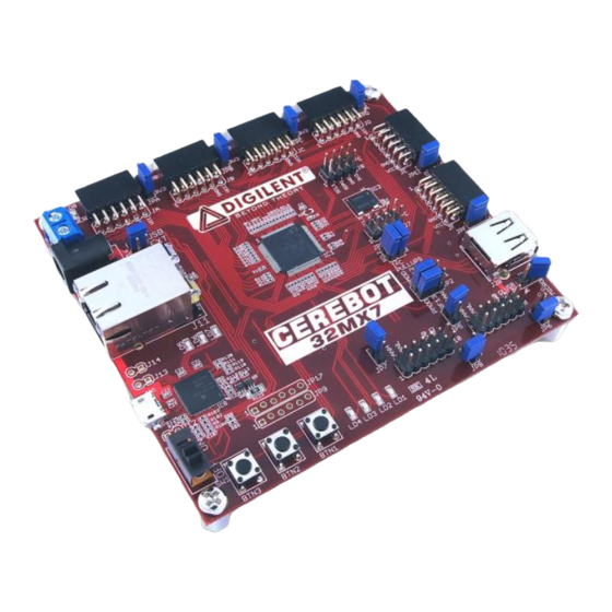
J20
USB Host Connector
This is a standard sized USB type A connector. This connector is used to connect USB
devices to the board when using the PIC32MX795 microcontroller to implement an
embedded USB host.
JP1 &
CAN or Pmod Select
JP2
These jumpers select microcontroller signals RF12 and RF13 for use with CAN #1 or Pmod
connector JF. Place these jumpers in the CAN position to use CAN #1. Place the jumpers in
the PMOD position to use then with Pmod connector JF.
JP3 &
Pull-up enable for I2C port #2
JP4
These two jumpers are used to enable/disable the pull-up resistors on I2C port #2. Insert
shorting blocks on these two jumpers to enable the pull-up resistors. Remove the shorting
blocks to disable the pull-up resistors. Only a single device on the I2C bus should have the
pull-up resistors enabled.
JP5
CAN #1 Termination
This jumper is used to enable/disable the 120 ohm termination resistor for CAN #1. Insert the
shorting block to enable the termination resistor, remove it to disable the termination resistor.
JP6
CAN #1 5V0 Enable
This jumper is used to enable/disable providing 5V to the CAN #1 connector. Insert the
shorting block to connect the board 5V0 supply to pins 9 & 10 of CAN #1 connector. Remove
the shorting block to disconnect the 5V0 supply.
JP7
CAN #2 Termination
This jumper is used to enable/disable the 120 ohm termination resistor for CAN #2. Insert the
shorting block to enable the termination resistor, remove it to disable the termination resistor.
JP8
CAN #1 5V0 Enable
This jumper is used to enable/disable providing 5V to the CAN #1 connector. Insert the
shorting block to connect the board 5V0 supply to pins 9 & 10 of CAN #1 connector. Remove
the shorting block to disconnect the 5V0 supply.
JP9
Do Not Use
JP10
USB host power select
This jumper is used to select which host connector is powered when host power is enabled.
Place the shorting block in the "MICRO" position to supply power to the USB micro-AB OTG
Connector, J19. Place the shorting block in the "A" position to supply power to the USB type
A Host Connector, J20.
JP17
Do Not Use
JA-JF
Pmod Connectors
These connectors provide access to the I/O pins on the PIC32MX795 microcontroller.
Digilent Pmod peripheral modules can be attached to these connectors.
JPA –
Pmod header power select
www.digilentinc.com
Copyright Digilent, Inc. All rights reserved. Other product and company names mentioned may be trademarks of their respective owners.
page 16 of 17
