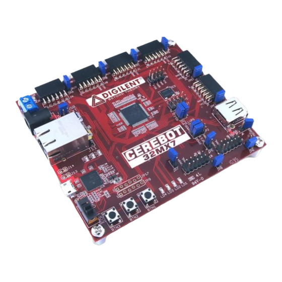
Digilent Cerebot 32MX7 Справочное руководство - Страница 6
Просмотреть онлайн или скачать pdf Справочное руководство для Материнская плата Digilent Cerebot 32MX7. Digilent Cerebot 32MX7 18 страниц.

Cerebot 32MX7 Reference Manual
the alternate) pins, and to use the RMII (not
the MII) interface signaling convention. These
options are selected using the configuration
variables in the PIC32 microcontroller and are
#pragma config
specified using the
statement. To enable the Ethernet controller in
the correct configuration, the following
statements must appear in the main program
module:
#pragma config FETHIO=ON
#pragma config FMIIEN=OFF
The LAN8720 PHY has a reset signal, labeled
NRST in the schematic, that can be used to
reset the PHY. This signal is connected to the
INT2/RE9 pin on the PIC32 microcontroller.
The NRST signal is active low. Configure the
microcontroller pin as an output and drive it low
to reset the PHY, or drive it high to allow the
PHY to come out of reset and begin operation.
The NRST signal is pulled low on the board, so
that the PHY is held in reset by default. To
allow the PHY to operate, this pin must be
driven high. This reset operation is not part of
the Microchip network protocol stack, and so
driving NRST high must be done before
initializing the Microchip network stack.
CAN Interfaces
The Controller Area Network (CAN) standard is
a control networking standard originally
developed for use in automobile systems, but
has since become a standard used in various
industrial control and building automation
networking applications as well.
The PIC32MX795 microcontroller contains two
independent CAN network controllers. These
CAN controllers in combination with two
Microchip MCP2551 CAN transceivers allow
the Cerebot 32MX7 board to operate on up to
two independent CAN networks. Refer to the
PIC32MX7XX data sheet and the PIC32
Family Reference Manual, plus CAN network
documentation for information on operation of
the CAN controllers and CAN networking in
general.
www.digilentinc.com
Copyright Digilent, Inc. All rights reserved. Other product and company names mentioned may be trademarks of their respective owners.
The PIC32MX795 microcontroller provides two
sets of pins that can be used to connect the
CAN controllers to the external transceivers.
The Cerebot 32MX7 is designed to use the
alternate (not the standard) pins. This selection
is made using the configuration variables in the
microcontroller, set using a
statement. To select the use of the alternate
interface pins, the following statement must
appear in the main program module:
#pragma config FCANIO=OFF
The pins on the PIC32MX795 microcontroller
used by signals for the CAN1 controller to
connect to its transceiver are shared with two
of the signals for UART3A and SPI port 3A.
Jumpers JP1 and JP2 are used to select the
use of these two signals. Place JP1 and JP2 in
the CAN position for use of the CAN1 network
interface. Place JP1 and JP2 in the PMOD
position for use of these signals for UART or
SPI operation. These signals connect to pins 1
& 4 of Pmod connector JF. When JP1 and JP2
are in the CAN position, Pins 1 & 4 of Pmod
connector JF are not useable.
There is no standard connector for use with
CAN networks. The Cerebot 32MX7 board
provides two 2x6 pin header connectors for
access to the CAN signals. Connector J9
provides access to the signals for the CAN1
network controller, and connector J10 provides
access to the signals for CAN2. Refer to the
schematic for the Cerebot 32MX7 board for
information on the connectors and signals.
Digilent 6-pin or 2x6 to dual 6-pin cables can
be used to daisy chain Digilent boards together
in a CAN network. A Digilent 6-Pin cable in
combination with a Digilent PmodCON1 Screw
Terminal Connector module can be used to
connect the Cerebot 32MX7 board to other
network wiring configurations.
The CAN network standard requires that the
network nodes at each end of a network
provide 120 ohm termination. The Cerebot
32MX7 provides the termination resistors and
jumpers to enable/disable the termination
resistors depending on the location of the
board in the network. Jumper JP5 is used to
#pragma config
page 6 of 17
